Essay: "How a Hole-in-the-Box Works - A Big Dig into Bass Reflex" - June, 1998 (Updated March 2001)
Even though loudspeakers utilizing bass reflex techniques (i.e., ported or passive radiator designs) are quite common, or maybe even the norm if you carouse the average audio/video retailer. There are, however, many misconceptions about how a bass-reflex system works. Most of these are either incomplete or flat out wrong. Here is a list of typical bits of misinformation:
-
Porting a speaker increases efficiency by allowing the back-wave generated by the driver to reinforce the front-wave.
-
Ported speakers have higher distortion than sealed enclosure speakers.
-
Ported speakers are more dynamic than sealed enclosure speakers.
-
The output of the port and woofer are out of phase with one another.
-
Ported speakers aren't accurate as sealed enclosure speakers because ports (and passive radiators) are resonant devices.
To effectively address these statements, and understand how a bass-reflex system works, we must first understand the real mechanics of how a cone speaker works. We've got the basics already explained in the primer (Volume 1, # 1, 1994, recently revised). Speaker cones are transducers. That is, they change an electrical signal into sound waves, in a reverse fashion of the way a microphone works.
A key to the transducer is that the electrical signal is represented by voltage, not power. This electrical force, throughout the normal working range of the loudspeaker driver does not represent the velocity or position of the diaphragm, be it a cone, a ribbon, or an electrostatic panel. Regardless of the mechanism, the basic physics are the same.
In order to accurately transduce an electrical signal into an acoustic pressure signal, the driver must do the following:
-
Apply a force on the diaphragm (cone) that is consistently proportional to the input voltage.
-
The diaphragm must accelerate in direct proportion to that force, regardless of position.
The second part is pretty easy for a free-floating object.
Newton's Second Law F=MA, or A=F/M (where F = Force, in Newton's, M = Mass, in Kilograms, and A = Acceleration, in Meters/Second/Second), shows that so long as the mass doesn't change, the acceleration will be directly proportional to the force applied. At first all is well in the audio universe. But how are we going to apply that force? Right, we need a motor. Cone speakers use a voice coil inside of a magnetic structure to do the trick. To learn more about the different kinds of motor structures used, and how they're built, please refer to the loudspeaker primer. (Actually, all three of Newton's Laws are applicable as to how well the speaker driver reproduces sound, but that is a story for another day.)
Now, this motor must satisfy the first requirement, that the force applied be directly proportional, or linear, as a function of the input signal. When power runs through the voice coil, the coil heats up. The more power, the more heat. As the coil temperature rises, so does the DC coil resistance, and as a result, the loudspeaker becomes less efficient. This results in power compression. That is, output that should be X dB higher than Y dB given a certain input level will actually be X-Z dB. Considering how much compression is applied (by the studio) in most modern music, this is of significant, but relatively minor concern.
More importantly, when voltage is applied and current flows, the induction of the coil generates a magnetic field, which pushes on the magnetic field of the magnet structure, and the magnets attached to the basket, or frame. In order to keep that force linear, and avoid distortion, the force between the coil and the magnet must stay linear regardless of the coil's position.
 However, in a real motor, the magnetic flux
density of the magnet structure gets weaker farther away from the center of the
pole piece gap where the voice coil rides. Loudspeaker driver engineers can
adjust the windings and the iron core used to concentrate the flux density to
compensate, there's still a finite distance where the coil can travel in the
motor which remains, for the most part, linear. That distance is called the
linear excursion, and can be described as either Xmax, which is the distance
from the resting position of the coil, or as a Peak to Peak number, which is the
total useable length (and sounds more impressive). It refers to the distance the
voice coil can move and still maintain the same number of voice coil wire turns
within the gap of the magnet pole pieces (see diagram on the right).
However, in a real motor, the magnetic flux
density of the magnet structure gets weaker farther away from the center of the
pole piece gap where the voice coil rides. Loudspeaker driver engineers can
adjust the windings and the iron core used to concentrate the flux density to
compensate, there's still a finite distance where the coil can travel in the
motor which remains, for the most part, linear. That distance is called the
linear excursion, and can be described as either Xmax, which is the distance
from the resting position of the coil, or as a Peak to Peak number, which is the
total useable length (and sounds more impressive). It refers to the distance the
voice coil can move and still maintain the same number of voice coil wire turns
within the gap of the magnet pole pieces (see diagram on the right).
The voice coil can physically move farther than that before slamming into some other part of the loudspeaker, but the Xmax represents the linear portion of its movement capability.
When the coil moves out of the linear excursion range, the non-linearity generates distortion. Because of this, we want the coil to stay in the center as much as possible. That's not likely to happen with a free-floating cone. Even just a little DC offset from the amplifier, or excursion into the less linear range of the gap, will send the cone and coil floating out to space. The mechanism used to center the coil in the gap, as well as bring the cone with it, is called the suspension. The suspension includes the surround and the spider which both act like springs to provide a restoring force, the magnitude and direction of which depend on the position of the cone and coil in relation to the rest of the speaker.
The variable force (magnitude and direction) added by the suspension, though necessary, mucks up our free-floating simple model where the only force resisting acceleration is provided by the inertia of the moving mass is constant. The force provided by the suspension is not constant by requirement. The force applied by the suspension, and the direction of that force, change with position, corrupting the net force applied to the cone. The more dominant the force of the suspension is, the greater the effect, which is to create a high-pass filter, or rather roll off the low-frequency response of the driver.
You could make a really loose suspension to minimize that effect. But if it's too loose, it would allow the coil to move into the less linear regions of the magnet structure's magnetic field very easily, letting the motor cause more distortion. If it's too tight, the speaker can't reproduce low frequencies. Loudspeaker driver engineers do the best they can to find a compromise that fits the purpose.
There is a point in terms of frequency where the resistance provided by the inertia of the moving mass and that of the suspension are equal. That frequency is the resonant frequency.
Above this frequency, the inertia dominates the resistance to acceleration. At higher frequencies, although the acceleration applied to the cone may be the same, because that force changes direction quickly, the cone travels very little, and so the suspension has very little effect. Remember, the net force of the suspension is proportional to the movement away from the center position.
Below resonance the opposite is true. While the inertia remains the same, as the excursion requirements become greater and greater at any given output level, the influence of the suspension increases.
To illustrate the point, imagine a bag of sand (or a beloved child ready for a real ride for the sake of science) on a swing. Like a speaker, a swing is a resonant system with mass and a restoring force. It's not a great analogy, since the restoring force is based on the pull of gravity on the mass of the child or bag of sand, but it's easy to visualize for this point. The important part is that the bag of sand, or child on a swing, is a resonant system.
Now imagine pushing (gently) the seat of the swing for ten seconds or so, gradually increasing force until 5 seconds, and then gradually decreasing force to nothing at ten seconds. You just applied half a cycle, and the passenger went slowly up, then came back to resting. Do it again in the other direction and you've just served as a good motor indeed. Notice that at the end of the ten seconds, your passenger is peacefully at rest, and wondering where the heck you learned to push a swing.
After completion of that fiasco, push just as hard (gently if you're using a live test subject) on the swing, but this time change direction of the pushing rapidly, so that you can get twenty pushes and pulls in during that same ten seconds. The someone may be looking at you like you really need some training, but the important thing to notice is that after those ten seconds, when you let go, there will be very little motion, if any.
When you compare the first two examples of pushing the swing above and below resonance on your VCR in slow motion, you will notice that with both, while you're pushing hardest, the bag of sand is farthest away from the center. The difference is that at 1/20 Hz, far below resonance, the hardest pushing is holding the sand against the restoring force of the swing. At 2 Hz , above resonance, the greatest force is being applied coincidentally with the almost inconsequential restoring force, countering the momentum it had generated while it was pushing in the other direction. In both cases, though they are phase shifted 180 degrees in relation to each other, there is no significant delay to the response of the swing.
If you push the swing the way you're supposed to do it, (you better start doing a good job before grandma hears about it,) you end up pushing at the resonant frequency. Notice while the first cycle will have very little movement, with each subsequent push, the swing will go higher and higher. Because this system has relatively little damping, at the end of ten seconds, the child or bag of sand and the swing will have stored energy into the system, and will be swinging with a bit of gusto, and probably won't be in the mood to stop. That's fine, because by then, it will be relatively hard to stop the swing. Like a swing pushed at the resonant frequency, a woofer stores energy. Hence, it resonates, as resonant devices tend to do.
(Note: Despite the myth of an amplifier's “damping factor,” amplifiers do not actively stop motion of the motor. A high-damping factor means a low output impedance. While the amplifier will shunt back EMF generated by the loudspeaker at resonance, providing electrical damping, this is no different in itself than if the terminals were shorted. In other words, if you want to increase the damping of a system, moving from an amplifier with a damping factor of 100 at a given impedance and frequency to an amplifier with a damping factor of 1,000 at the same is a relatively futile exercise of numbers, because at that point, the damping of the loudspeaker system itself will dominate.)
That's why speakers have brakes themselves, referred to as damping, in the electrical and mechanical elements that compose the structure. Larger magnets impose a greater braking force as the coil cuts through the magnetic field, and turn the motion into electrical current in the same way that the speaker turned current into motion. Any decent power amplifier then shunts this current. Frictional losses in the suspension absorb energy and turn it into heat.
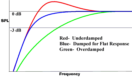
Damping is described mathematically as a Q value. In loudspeakers, it describes the ratio of energy storage at resonance, to dissipation. The electrical properties have a Qes. The mechanical properties have a Qms. When both are combined to the cabinet's Q value, a system Q is derived. High Q systems store energy for a long time, resulting in a longer delay and higher amplitude at resonance, while low Q systems get rid of energy quickly, providing a shorter group delay and a lower amplitude at resonance.
Damping in a speaker is absolutely critical. Otherwise, near the resonant frequency, rather than stopping, the woofer would go BOOOOOMMM, as well as bottom out, and destroy the voice coil former (a tube on which the coil is wound).
 At
the same time, though, too much damping limits output, especially at resonance,
and rolls off the low frequency extension that would otherwise be possible by
the driver at the same resonant frequency.
At
the same time, though, too much damping limits output, especially at resonance,
and rolls off the low frequency extension that would otherwise be possible by
the driver at the same resonant frequency.
In an acoustic suspension, sealed box, or infinite baffle application, there is an optimum system Q value to obtain the flattest frequency response, and a phase response identical to a 2nd order Butterworth filter. Not coincidentally, the roll-off is identical to a 2nd order Butterworth filter at 12 dB, which also not coincidentally is the inverse effect of room gain boost due to the room dimensions shorter than ¼ of a wavelength providing a pressure cooker effect. Weird eh? Even weirder, is that this Q value is approximately 0.71, or exactly half of the square root of 2. Hmmm. Maybe there's something to math after all…
Note that in the graph above, the Q value affects the output at resonance, but not much above or below. The resonant character, in fact, has no effect on efficiency, which is determined by the strength of the motor and the mass of the cone, as well as the radiating area of that cone.
Now that we all understand how woofers (and tweeters for
that matter) work as resonant systems, it only takes a skip and a hop to see how
bass reflex systems work.
A port, or passive radiator, acts as a secondary resonant system, attached
loosely to the first. If it were rigidly connected and could instantly follow
the movement of the active driver, it would be 180 degrees out of phase, not due
to a delay, but to the mechanics of their coupling, much like a seesaw. Instead
of one going up while the other goes down, down is in and out is up.
Above Resonance
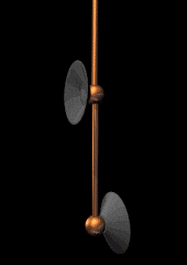
The air mass provided by the box volume and the port, or the passive radiator, can't react instantly to the pressure induced by the active speaker. Above its own resonant frequency, it's too slow (upper bandwidth limited) to suck any energy off the active driver, and it does almost nothing at all, refusing to move when the direction of force changes too rapidly. This is shown by the animation on the left, upper. (For all three of the animations shown, the driver on top is active, while the driver on the bottom represents air in the port, or a passive radiator. The pendulum bar in between the two drivers represents air within the enclosure.)
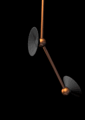
At Resonance
As the active driver approaches the tuned frequency of the secondary resonant device, that device begins to actually suck energy so forcefully through the internal air pressure, that it loads the active driver. It uses the cone as the fulcrum to bear the force of its own acceleration, thereby limiting the active driver's excursion, and transferring the greater output to its own opening or surface.
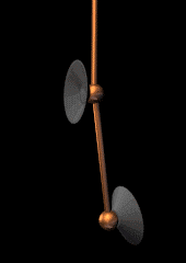
Below Resonance
Below resonance, the reflex system backs off on loading the active driver, yet still moves quite a bit. But since it is merely venting the back-pressure instead of "cracking the whip," it's no more than a hole in the baffle, which causes cancellation with the active driver's front output. Because of this, the output rolls off very steeply, at 24 dB per octave (over 200 times less output per halving of frequency.) Also, since the port does not limit excursion and the suspension force that would have been provided by the compliance of air in a sealed system doesn't exist because of the “leak” in the enclosure, the active driver can very easily “bottom out,” or smack itself into itself, below that tuned frequency.
I should note that one can't simply punch a hole in a sealed enclosure, put a pipe of whatever length will fit, and have a bass reflex enclosure that will yield a flat response. The output of the port and the driver at roll-off must be shaped so that they can be added correctly. Because the Q values of the reflex system and the active driver determine the shape of their response, in order to change from a sealed to a ported design, or vice versa, the cabinet, driver, or both must change.
So what does all this mean anyway?
First off, bass reflex systems provide a tool to compensate for the enclosure size/efficiency/low-end extension catch 22. Because of the physics of suspension systems, and the compliance of air, regardless of the size of the magnet or cone, three relationships can always be counted on:
-
To increase efficiency, you must lose extension and/or increase cabinet size.
-
To decrease cabinet size, you must lose extension and/or efficiency.
-
To increase extension, you must lose efficiency or increase cabinet size.
While compromising with a sharper 24 dB/octave roll-off which makes output below the tuned resonance essentially unusable, a bass reflex makes the following possible in comparison to a sealed enclosure:
-
A system of 3 dB greater efficiency without sacrificing extension, defined by the –3dB point, or cabinet size. It doesn't make the driver more efficient, but it extends the bandwidth of a more efficient, over-damped driver (bigger magnet, lower Qes).
-
A decrease in cabinet size by 50% without sacrificing extension, again defined by the –3dB point, or efficiency.
-
An increase of low frequency extension by 1/3 of an octave, sometimes more, depending on the compared sealed alignment, while maintaining the same efficiency level or cabinet size.
In addition, the loading of the driver by the reflex system, which limits excursion, also makes the active driver do most of its work in the more linear range of the motor. This equates to less distortion at and a little above the tuned frequency, and more potential output in the case of a port because ports have no excursion limits. That's a pretty substantial benefit. Why doesn't everybody do it then? Well, like everything, there's always a cost.
For starters, there is the aforementioned roll-off inherent to reflex designs. A sealed enclosure still has significant output after its –3 dB cutoff frequency. In fact, that roll-off can complement room response to yield flat output far below cutoff. Ported designs can't do that. On the other hand, if they go deep enough without the room, they don't need to.
Also, a large volume of air pushed through a relatively small opening may generate turbulence, or a chuffing sound. Ports can be shaped (flared at the openings) to limit turbulence, however, so the compromise doesn't have to arise, but must be dealt with. Passive radiators don't suffer from that problem at all but, unlike ports, they do have excursion limitations. Believe it or not, I once ripped a passive radiator apart with "Public Enemy" pumping a 30 Hz WHOOOOSH, WHOOOOSH, WHOOOOSH, WHOOOOSH, through concrete hard enough to make your vision blur if you leaned your head against the wall from the adjacent room. I think that the school housing department really misses me.
Because ports are part of a fourth order system (two second order resonant devices), getting a frequency response within certain tolerances requires a greater attention to manufacturing tolerances than with a second order sealed system. This incurs a higher rejection rate (and cost) for drivers, as well as placing higher manufacturing demands on cabinets. If the port or passive radiator is tuned a few Hz away from the ideal frequency due to a slight change in cabinet volume, it can have profound effects in the frequency response (dips or peaks.). Sometimes, manufacturers intentionally mistune the port to give a rise in order to fake greater extension. Because of this, bass-reflex speakers can often sound boomy, even if they don't have to.
The phase response, which is sometimes referred to as transient response, will be slightly worse at cutoff in a ported system than in a sealed system. This can result in "slower," or more accurately, "more delayed" sounding bass. But, at the same time, since it will go deeper than a sealed system with the same efficiency and cabinet size, and tends to use a more damped driver, the larger phase error at the tuned frequency may be less noticeable if it can go deep enough. So, subjectively, it could then sound faster.
Another aspect of loudspeakers which bass-reflex systems handle differently than sealed systems is the changing characteristics of the loudspeaker as a function of power output. As power input increases, the voice coil heats up. As the voice coil heats, the DC resistance rises, the impedance changes, and the electrical damping lessens. While a sealed system's output will remain relatively consistent, with perhaps a minor change in the roll-off curve (with more output near system resonance,) the ported system's relationship between the port (or passive radiator) and the active driver will change more dramatically. As a result, if the system was optimized for a flat response at a low-level output, the frequency response will suffer at high outputs. I've heard from knowledgeable loudspeaker engineers that because of this, systems designed for VERY high output, a.k.a. sound reinforcement, are actually tuned based on the driver's parameters in high-temperature scenarios. Usually, in the home environment, a manufacturer will optimize the tuning for lower output levels.
In addition, the size of the port itself, regardless of tuning frequency, can have quite an effect. A small port, although it does not have to be very long, must move a lot of air through a very small opening. This make turbulence more of a difficult thing to cope with. But, it also makes for a more non-linear resistance to air movement. In other words, as output increases, the resistance to air flow increases, and the benefits of a port decrease, making the output look more like a leaky sealed system. The larger the port, the less it happens, but the characteristic is always there. Very large ports, say 4 inches wide, will be FAR more linear in this regard than a port, say 1 inch in diameter. However, as the surface area doubles, the required length doubles as well, so that a port 4 times wider in diameter, which has an opening 16 times greater in surface area, must be 16 times as long to maintain the same tuned frequency. On top of that, large ports may suffer from pipe resonance (like a pipe organ) which can be really annoying.
And which is better? As you can see, there is no inherent superiority to either, and even within a single category, many options await. In the end, it depends what you want, and what the manufacturer is willing to do to give it to you. Each approach has its own advantages and disadvantages, and each designer will choose their own way to work with, or around, those features. There are numerous examples of really bad, and really splendid implementations of both. The shopping I leave to you.
- Colin Miller -
© Copyright 1998 - 2001 Secrets of Home Theater & High Fidelity
Return to Table of Contents for this Issue.
Magazine Publishing Solutions by