DIY Project # 5 - The Thrifty Thumper (Subwoofer) - November, 1997
designed by Robert Trim and built by Robert & Jason Trim
![]()
(If you would like to have your DIY project published in Secrets, please E-Mail Ralph Calabria at [email protected].)
About the Designer by Ralph Calabria
Robert Trim is Director of TV Productions for Salt Lake Community College in Salt Lake City, Utah. His audio experience goes back to the days of Heathkit built-it-yourself amps and tuners, through the Quad stereo era and 19 years of professional audio and video production. Bob shares with us his "Thrifty Thumper", so dubbed because this subwoofer is relatively inexpensive to build while still dishing out its fair share of lower-octave output. The sub is a sealed enclosure design with the cabinet tuned to 31 Hz. Our hats go off to Madisound Speaker Components for providing the DIY sector with a low cost, 12" dual voice coil driver that delivers the goods. This project is proof that you don't have to spend a bundle to get good, deep bass ( you just have to build it yourself!)
Table of Contents (you can click on the list to go to specific item)
Project Overview
Project Design
Construction
Assembly Tips
Wall Padding and
Cabinet Stuffing
The Crossover
Sealing up the Box
Installing the Driver
All-together-now
Specifications
Cabinet Finishing
Late News
The ultimate goal was to enjoy what is probably the most significant improvement one can make to an existing hi-fi system. That is the addition of a speaker that will realize the depth of those really low notes or frequencies now mixed into CDs, movies, even weekly TV series. If you haven't heard Babylon 5 or Voyager or Xena with a subwoofer connected to your system, your missing a lot of sound, special effects and texture woven into these and other shows.
My goal, as a hard-core, life long Do-It-Yourself'r was to design and build one of these subwoofers on the cheap, without the end result being something worse than you can find mass produced in the stores. I also wanted a project that could be easily duplicated by just about anyone who has a table saw, router and a spare weekend. There was an underlying motive as well. My teenage son, Jason, needed to work on some basic math skills. So the practical application of a little algebra, construction math, etc. was right there in this project, not to mention that his Metallica CDs would sound... well.... heavier metal.
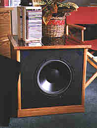
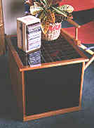
On the design side, I wanted a cabinet that would be a piece of furniture . . . an end table to be exact. So it had to measure out in height, depth, and width. Now, I know the "furniture" concept makes those of you who have not had your hand in wood finishing a little squeamish. Hang in there, it's not that bad!
The driver had to have specs that would allow it to reach down into those "T-Rex" footsteps, represent the string bass with clarity, and not sound like a cardboard box instead of a tight kick drum. I was after a smooth, even driver that was reasonable on the pocketbook. In fact, I wanted the whole project to come in at $150 to $175 U.S. You can double the price easily if you do fancy finish work or use exotic woods on the outside. That's your choice, and far enough down the construction road for you to ponder a bit.
I wanted only one subwoofer for our stereo system, so the driver had to have a dual-voice coil. There are several out there to choose from, and I settled on the house brand from Madisound. They have 8" through 15" woofers, but the DVC 12" caught my eye. It's specs are quite nice.
Madisound 1252DVC
12" diameter
Impedence: 8 ohms/coil
Power handling: 100 watts both coils driven
Efficiency : 92 db/w/m
Fs = 15 Hz
Vas = 533 liters
Qms = 4.1
Qes = 0.39
Qts = 0.36
Madisound takes the initial pain out of design by offering several alignments and their outcomes. For example, in a relatively small sealed enclosure of 85 liters, you achieve 32 Hz. On the other end, if you build a 142 liter box and port it with a 3"x11" tube, you get 26 Hz out of the configuration.
The driver is a stamped frame, polycone, foam surround construction. This is very common in less expensive drivers, and has its inherent problems. For the most part, these problems can be overcome if the system is properly designed.
The final decision was to make it a passive system, that is, no amplifier or crossover built-in. Again, this was a compromise, but you can change this as you build without any major incantations. So, on with the project !!!
The box itself is
"falling-off-a-log" simple. You will need the better
part of a full sheet of 3/4" MDF. Common particle board can
be used, but MDF cuts and finishes much more easily. Now, you
must make a decision here before cutting. Do I want tile on top
or do I want something else on top (like wood veneer)? Maybe just
carpeting the cabinet or covering it in Formica and standing it
the corner. In order to have tile on top, the top must be a
certain size so you do not have to cut the tile to make them fit.
 If you do not want tile on top, cut to the
dimensions according to Box One. This box has a lower profile and
is slightly narrower. The tile will fit on Box Two. It is closer
to standard end table height when finished.
If you do not want tile on top, cut to the
dimensions according to Box One. This box has a lower profile and
is slightly narrower. The tile will fit on Box Two. It is closer
to standard end table height when finished.
The following pieces will be needed for the
basic speaker cabinet:
Box One (no tile) |
Box Two (with tile on top) |
|||
| 4 | 16.5" x 19.5" | (inner baffle & back) | 4 | 18" x 17.5" |
| 4 | 18" x 21" | (outer baffle & back) | 4 | 19.5" x 19" |
| 2 | 21" x 22" | (sides) | 2 | 19" x 22" |
| 2 | 16.5" x 22" | (bottom & top) | 2 | 18" x 22" |
| 1- 5" | 4" x 4" | (fence post)* | 1- 12" | 4" x 4" |
- *You can also make the cabinet 1" shorter and leave the 4 x 4 out.
The following are the same for both
cabinets:
QTY. |
Material |
| 1 | 1" x 1" x 10' pine (cleats) |
| 1 | 1 5/8" dia. x 8' wood closet pole (bracing) |
| 1 | tube liquid nails and caulk gun |
| 6' | 30# roofing felt |
| 1 lb. | 2 1/2" sheet rock screws |
| 1 | 50/50 wool & polyester blend pillow (found at WalMart) |
| 4' x 4'x 3/8" or thicker carpet rebond | |
| 1 | cup w/binding posts Madisound #TD-CUP |
| 1 pkg. | weather stripping |
| 6' | heavy zip cord (12 gauge or heavier - Radio Shack has heavy speaker wire which works well) |
| 1 pkg. | Spade connectors (again Radio Shack has these in various sizes) |
If you wish to finish the cabinet as shown
you will also need:
QTY. |
Material |
| 1 | 1"x2"x8' mahogany (top edge trim) |
| 1 | 3/4" x 3/4" x 8' mahogany inside molding |
| 1 | 3/4" x 3/4" x 8' outside corner molding. Oak over pine or solid oak |
| 1 | 3 1/2" decorative door molding. Oak over pine or solid oak |
| 4 | 50 lb. capacity casters. |
| 1/2 sheet | 1/4" oak plywood |
| 1 | Small can of good Honey Oak stain (or whatever color you prefer) |
| 1 qt. | Behr Water Base Crystal Clear Polyurethane, high gloss or Carver-Tripp water base Polyurethane |
| 4 | 12" x 12" sheets of 2"x 2" black tile. (Color Tile was my source) |
| 1/2 lb. | black tile grout |
| 1 qt. | latex tile grout solution |
| 1 qt. | tile mastic |
| 1 | grooved tile trowel |
| 1 qt. | contact cement (I used one of the new water based ones) |
Sides & top - Align sides and
top and drill pilot holes with a bit that has a countersink
collar. Make sure all screws are installed below the surface by
about 1/16". Run a good bead of Liquid Nails on each joint
and screw it together. Make sure everything is square. Front
baffle - Lay the larger baffle on flat surface. Place the
sheet of roofing felt on top (pre-cut to the same size as the
baffle). Lay the smaller baffle on top of the felt and set
approximately centered on the larger baffle. 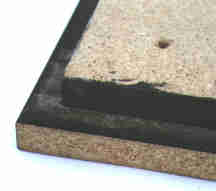 Now place the
box face down on top of the baffle sandwich so the smaller baffle
fits inside. Slide things around until the larger baffle is
centered and square on the box. Reach inside with the drill and
make three pilot holes for screws. Make sure these holes are
outside of the middle 12" of the baffle. Screw the baffles
together. With the baffle tagged together, you now need to draw
your outline of the router cuts for the speaker. One cut, the
inner circle, is all the way through both layers. The second pass
is to cut an inset lip for the driver to recess into. Refer to
the drawings for details on measurements. Note that this rabbit
cut is about 3/8" deeper than the edge thickness of the
driver. The extra depth will be taken up with a foam strip/gasket
to isolate the driver from the cabinet.
Now place the
box face down on top of the baffle sandwich so the smaller baffle
fits inside. Slide things around until the larger baffle is
centered and square on the box. Reach inside with the drill and
make three pilot holes for screws. Make sure these holes are
outside of the middle 12" of the baffle. Screw the baffles
together. With the baffle tagged together, you now need to draw
your outline of the router cuts for the speaker. One cut, the
inner circle, is all the way through both layers. The second pass
is to cut an inset lip for the driver to recess into. Refer to
the drawings for details on measurements. Note that this rabbit
cut is about 3/8" deeper than the edge thickness of the
driver. The extra depth will be taken up with a foam strip/gasket
to isolate the driver from the cabinet.
I made a third pass on the back side of the baffle with a 1/2" 90 degree edging router bit to open up the baffle on the inside of the box. This will allow the woofer to breath better.
Rear panel - Do much the same thing
as with the front baffle. Sandwich the roofing felt and tag the
layers together with screws. The hole in the back for the
connector cup is centered in the lower third. 
Cleating & bracing - The design of the front and back is self-cleating. The cabinet sides are where I ran the 1" x 1" cleats. Put a good bead of Liquid Nails along two sides of each cleat and hold them in place with 1 1/2" finishing nails.
Cut 2 pieces of closet rod to fit top-to-bottom and 2 for side-to-side in the cabinet. Cut them so they have to be force fitted. Place them according to the plans with a dab of glue. If you cut them so they fit loosely, glue in place and run a screw from the outside to pull them together tightly.
Once you have the sides, top, and bottom glued and screwed together, and the holes cut for the woofer in the baffle and the cup in the back, it's time to put it together.
Wall Padding and Cabinet Stuffing
There are many schools of thought regarding this topic, but we won't wade into that here. What follows is what we did, and it worked well for this speaker.
Line the bottom and one side with 2 layers of roofing felt, precut to lay in and around the crossbraces. Staple in place but do not staple it to death. You want it to be free to move. For the other side, top, back and inside of the baffle (around the woofer hole), glue a layer of carpet rebond. This is the stuff that looks like chunks of foam rubber that are glued together in a sheet and put down under carpet. There is also a hemp-like underlayer that will work just fine. Use hot glue or liquid nails to glue in place then staple in a few places for good measure. The stuffing can be done after the crossover is in and wiring done, but here is what you will do. Cut open the pillow and slide out the stuffing. It is probably rolled up to form the pillow shape. The pillow weighs about 2 lbs., and you need about 1/3 of that. If you unroll the stuffing and measure off 1/3 and cut it off, this will be very close to the right amount. The stuffing is going to be used to break up the sound traveling around inside the cabinet. Often, stuffing is used to make a small cabinet "appear" larger to the driver. Our cabinet is actually a bit larger than the right size, so the concern here is damping internal reflections.
Pull at the stuffing to "fluff-it-up" a bit and make it more even, then place it centered in the cabinet between the cross braces. You can staple a few places to the sides, top, and cross braces to keep it in place. It should look like a cloud in the middle of the cabinet.
The plan for our situation was to have a speaker that rolled off easily to match the satellites. A simple second order, passive configuration was perfect. I also wanted it to be passive because the amp we are using for a second set of speakers (B channel) could be used actively with the A channel. Some people like higher order crossovers so that high frequencies are kept out. High frequencies and polycone woofers do not go well together. It also depends on your room, satellites and how low they go. Mine roll off at 100 Hz, and are a bit thin there to boot. So the crossover is designed to start a 12 dB/octave suppression at 100hz. The extra overlap from the sub up to 250 Hz was not only welcome, but it added a full sound quality to the room and system. I used a first order crossover at 62 Hz. The value for the inductor was 18mH.
If your amp/receiver has a Sub Out that is pre filtered, you can skip the crossover, BUT your wiring will be a bit different inside the cabinet. Sub Outs can be either mono or stereo. If yours is mono, you have two choices on how to wire your sub.
You can take the mono Sub Out into a second mono amp, then to the sub with both coils wired in parallel (+ to +, and - to -). This provides the most efficient output from the driver, a 4 ohm load (the amp should have a good power suppy for this method). Or, you can use a stereo amp, switched to mono, and drive both woofer coils independently, an 8 ohm load per channel. If your Sub Out is stereo, it's pretty simple to run connectors from the Sub Outs of the amp driving your satellites to the inputs of the sub amp and then to the sub.
Passive crossovers (crossover between the power amp and the speaker) for low frequencies are expensive. You are dealing with large inductors, and they are not cheap. In fact, you can go to an active crossover (between the preamplifier and power amplifier), but it's a bit more of a hassle. Actives are more efficient, and your sub will have more output per watt. It's really your choice. The formula for a simple first order passive crossover for the sub is L = R/6.28f, where L is the inductor value in Henries, R is the impedance of the driver, and f is the desired crossover frequency. If a frequency of 60 Hz is chosen, the inductor would pass frequencies to the driver at the input level below 60 Hz, and roll off at 6 dB/octave above 60 Hz, i.e., 6 dB down at 120 Hz, and 12 dB down at 240 Hz. The inductor is placed in the + portion of the signal path.
You can use hot glue or Liquid Nails to hold the inductors (low pass to subwoofer driver) in place on the bottom of the sub cabinet. I soldered the capacitors (high pass to the satellite speakers) in place to the various leads. Nothing fancy because there are so few parts. The heavy zip cord has spade connectors on one end that are connected to the binding posts on the inside of the cabinet, soldered to the inductors, then a second run from the inductors to the woofer. Again there are spade connectors crimped and soldered on both ends. HINT: use a felt pen to mark the "+" lead on both the binding post end and the speaker end of the wiring. It makes life easier later on.
Glue and screw the back in place (see the cabinet drawing for screw pattern). Glue and screw the baffle in place.
Now we will deal with those fence posts
previously mentioned in the parts list. The cabinets are
oversized by a few hundred cubic inches. This is intentional. The
bracing, crossover parts and the woofer itself occupy space
inside the cabinet, but not enough to offset the volume required
to make this an end table. 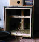 So, we displaced some space with wood blocks.
Squeeze lots of Liquid Nails on the bottom of the piece and press
it in place about mid-way in the cabinet bottom. If it rests,
touching a bracing dowel, put some glue on the dowel and press
the block against that as well. Depending on which cabinet
version you are building, install the appropriate piece.
So, we displaced some space with wood blocks.
Squeeze lots of Liquid Nails on the bottom of the piece and press
it in place about mid-way in the cabinet bottom. If it rests,
touching a bracing dowel, put some glue on the dowel and press
the block against that as well. Depending on which cabinet
version you are building, install the appropriate piece.
A little explanation on the concept of
"decoupling" (isolation) is appropriate here. A big
empty box will vibrate unless we interfere with the source of the
vibration, i.e., the driver. The design for the baffle and the
back is called "constrained layer". Simply put, we have
sandwiched something between both panels that has very different
resonance characteristics than the panels. In our case, it was
roofing felt. Speaker designers have used sand, dry wall, Baltic
birch plywood, and other materials to form a sandwich panel that
is acoustically "dead". If you rap you knuckles on the
side of the cabinet, then on the front, the difference should be
clearly audible. 
First we must do some modifications to the driver itself. Remember the comment earlier about the stamped frame? Stamped frames vibrate, but they are cheap to make and reduce the cost of the driver. My way of fixing this may not be available to you, but there are alternatives. I have 200+ pounds of 1/16" lead sheets lying around. It doesn't move a lot for obvious reasons. I cut enough strips the width of the basket legs to glue 2 layers onto the basket. I smeared a layer of Liquid Nails on, set the first piece of lead in the glue, glopped on more glue, and laid the second layer on top. If you don't have lead, there is a material called DynoMat that can be attached to the basket, or a quick trip to the local auto stereo installer will get you either a gloppy coating or a rubber-like mat that can be applied to the basket. This will change and reduce the resonance of the basket.
Now, run a length of the weather stripping on the lip of the baffle where the driver will mount. This further isolates the driver from the cabinet. I went one step further by mounting the driver with sheet rock screws that had small rubber washers between the screw head and the driver. You only need to snug the driver into the weather-strip gasket when mounting. Be sure to pre-drill pilot holes for the screws.
Here is where you make the critical "what will this thing will look like" decision. If you are going to finish the cabinet with paint, Formica, or as shown, in oak, you can dry fit everything, fire it up and give it a listen. Then pull off the driver and terminal cup to do the finishing work. But let's assume you want to give it a listen while you ponder the outside.
The rear cup is ready to be installed.
Connect the spades from the crossover, slip into place and screw
down. Again, make the cup snug, not "killer tight". 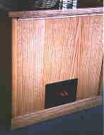 Overtightening will deform or crack the cup. Set the cabinet on
its back. Hook the wires to the driver and drop it in place on
the baffle. Screw it in place. If everything was wired correctly
you should be ready to make low notes. This driver needs some
time to be broken in. It gets considerably better with age. We're
talking about 8 to 15 hours of playing fairly loud, low notes. If
you have a way of generating a 50 Hz or lower continuous note, do
so with about 25 to 35 watts of power. This isn't pleasant to be
around so do it when everyone is gone shopping or something. The
conditioning may be done in stages. You may even do it with the
driver lying on the floor face up, while you are building the
cabinet. This option is far quieter!
Overtightening will deform or crack the cup. Set the cabinet on
its back. Hook the wires to the driver and drop it in place on
the baffle. Screw it in place. If everything was wired correctly
you should be ready to make low notes. This driver needs some
time to be broken in. It gets considerably better with age. We're
talking about 8 to 15 hours of playing fairly loud, low notes. If
you have a way of generating a 50 Hz or lower continuous note, do
so with about 25 to 35 watts of power. This isn't pleasant to be
around so do it when everyone is gone shopping or something. The
conditioning may be done in stages. You may even do it with the
driver lying on the floor face up, while you are building the
cabinet. This option is far quieter!
As expected, this configuration measured out fairly well, but sounded better than the specs indicated. Bass speakers are very sensitive to their environment. A driver that sounds thin and weak in one room, may kick tail in another. It all depends on the room dimensions and the volume at which it's played. This driver got its public debut in a 300 seat auditorium where a multimedia presentation was being done. The soundtrack had several very low frequency sequences. A heart beat, a large native drum, etc. After several placements, the system coupled with the room and came alive. Full, rich, non-boomy bass was emitted. This particular theater has never had a good sound system, so there were many questions like "where did all that low sound come from?" Here are the in-room response measurements.
| Hz | SPL Meter |
| 16 | -10 |
| 20 | -6 |
| 31 | 0 |
| 40 | +2 |
| 50 | 0 |
| 63 | -2 |
| 80 | -4 |
| 100 | -4.2 |
I used a Radio Shack SPL meter to measure in-room (listening position) and very close (3" from the center of the driver, in room) response using a frequency sweep. The readings have been compensated to reflect the error in the meter at each frequency shown. You will note the peak at about 50 Hz in the listener's position. Our TV room has a standing wave measurement at that frequency. Again, subs and their environment are closely knit.
This is up to you. The photos here show the MDF covered with 1/4" oak plywood. This is the stuff cabinetmakers call "skins". You can also use paper-backed veneer. Here are some finishing tips:
- Use a latex contact cement and follow directions. 2 coats on both surfaces.
- Make sure that all surfaces that you are going to attach veneer or oak plywood to are flat! NO bumps. Use a belt sander to finish down high spots.
- If screw holes are low, fill with auto body putty. Get it in a tube at the local Checker or Auto Zone. Sand flush.
- I used water based polyurethane for the first time and liked the results. It went well over the stain. Follow every direction to-the-letter. The biggest problem is air bubbles. Brush on slowly with a synthetic brush. Three coats looks great. Sand with 400 grit prior to the last coat. Watch for runs.
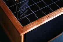
- The tile work is very easy, but you must
be careful with the black grout. It stains the wood. 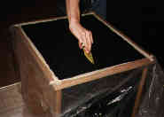 Mask the top edging (mahogany) off with masking tape and plastic
sheeting. Most tile stores (I went to Color Tile) will be of
great assistance in making the project come out perfectly.
Mask the top edging (mahogany) off with masking tape and plastic
sheeting. Most tile stores (I went to Color Tile) will be of
great assistance in making the project come out perfectly.
- The finish edging or skirting on the cabinet is oak door molding. It is blocked in several places underneath to strengthen it.
- The wheels (casters) are 50-pound rated. Use of casters will make vacuuming under the beast a lot easier.
- Our cabinet does not have an oak finished front because we decided to put a grille on it. If you do want the front to be finished, there is a handy router bit that will track in the speaker cutout and trim off the oak perfectly. Ask in the tool department of your local hardware store for a drywall cutter bit. It is used to cut out light-switch holes and such. It's a straight piece of steel with a section cut out of it.
- The top edging is mahogany 1" x 2". The darker wood as a step between the honey-stained oak and the black tile is quite eye catching. The trick here is to route a notch in the mahogany where it attaches to the cabinet edges. This allows for more "glue area" when attaching. People like to pick up furniture like this by the edges, and this baby is heavy. Having an edge separate from the cabinet would be less than desirable. Sink a couple of finishing nails in for good measure as well.
We have now provided the sub with its own amp. We did a little pawn-shop cruising and found a late 1970s Pioneer 70 watt/channel receiver in pristine condition for $40.00. We wired a cable from the Yamaha headphone out to the Pioneer's AUX inputs. We set the volume on the Pioneer to a level that sounded about right after listening to lots of stuff. Now with the sub amp being driven from the headphone output of the primary amp, when we change the volume of the Yamaha, the sub changes as well. This is not a good impedance match, however, but this will be tweaked later, For now, it sounds great.
The overall sound is better as well. There isn't a big power drain on the primary amp to drive the sub. We have found that the 50 watt limit per voice coil when driven separately is very true. This driver will bottom out if driven at moderate levels with the loudness switched on.
How has it performed over the past 5
months? Very well, thank you. We went through many different
stuffing gyrations, placements, more-and-then-less 4" x
4"s inside to correct the oversizing. It made quite a
difference in the smoothness of the response. If all you have
listened to has been the bandpass units in TV showrooms, this
Thrifty Thumper will be an eye . . . make that ear opener.
It has bass notes that you can live with. And my son says that
"Even that jazz stuff you listen to sounds better,
dad". That's sayin' something!
Robert Trim
![]()
© Copyright 1997 Secrets of Home Theater & High Fidelity
Return to Table of Contents for this Issue.
Magazine Publishing Solutions by