8. Test fit the drivers in the holes you just cut and
adjust if necessary.
9. With the driver in the cutout, for both the Front
panel and the Isobaric Top, mark the locations of the screws along the
perimeter of each driver.
10. Drill though each panel at the location of each
screw. The drill bit size used should match the diameter of the screws your
will be using.
Tip: Keep drill perpendicular to the panel.
 11. Working from the inside (as you marked earlier)
of the Front panel and Isobaric Top, mount the T-nuts in the holes you just
drilled. You'll need to slightly enlarge each of the holes you just drilled
for the screws to a depth of the T-nut (depth depends on the T-nut used) in
order to countersink the nuts. Test fit your depth on one of the T-nuts. If
correct, smear a little of the Gorilla Glue on the nut and tap into each
hole.
11. Working from the inside (as you marked earlier)
of the Front panel and Isobaric Top, mount the T-nuts in the holes you just
drilled. You'll need to slightly enlarge each of the holes you just drilled
for the screws to a depth of the T-nut (depth depends on the T-nut used) in
order to countersink the nuts. Test fit your depth on one of the T-nuts. If
correct, smear a little of the Gorilla Glue on the nut and tap into each
hole.
Tip: The glue serves a number of purposes: sealing
around the nut, reducing any possible of vibration of the nut, and
(practically) to ensure that the nut does not fall in the cabinet if the
drivers are removed.
12. Repeat steps 8-11 to mount the two 2" ports in the
Top panel.
Tip: Use the top portion of the flared port as a guide.
Mark the proper
screw locations in the plastic.
Tip: Align the screw holes along the center line of
the top of the box you drew earlier.
Tip: Make sure to use the T-nut with the correct thread! Since we chose to
use different screws to mount the ports (round head black Phillips) than we
did for the drivers, there's a chance for using the wrong thread.
13. On the Bottom panel, mark a point in each corner
2" from each edge for the mounting of the spike feet. Pre-drill the mounting
hole for the spike feet per the instructions provided with the feet.
The kit I listed comes with T-nuts, so be sure to
follow the tips I listed earlier as you install them.
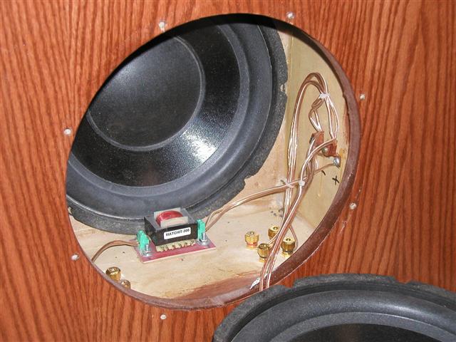
14. On the Back panel of the box, using the WBT
binding posts as a reference, mark and pre-drill the holes for the external
binding posts 5" from the bottom of the box along the centerline.
Also, glue the backside of the mounting kit to the inside of the panel to
ease later assembly.
15. Cut the 1" oak dowel rod into two lengths. For
the length, I'd suggest matching the dimensions of the Bottom panel.
16. Assemble the bottom portion of the ports per the
directions included with the ports. DO NOT glue the top flare on yet!
17. Dust off and set aside the pieces, you'll need
them all later.
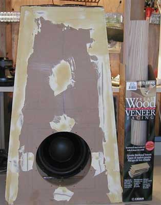
Pre-Assembly - Does it look like the
Picture?
With everything measured and cut, pre-assemble the
box to see how things line up. Now's the time to find out if any mistakes
were made!
18. Assemble the entire outer box. Starting 1"
from each side and every 4" thereafter, attach the adjacent panels with
countersunk screws. At this point do not glue the box together, you may need
to disassemble things
Tip: When assembling the box sections, keep in mind
the final dimensions of the box. For example, the front and back panels will
overlap the sides, and the thickness of the front and back panels plus the
width of the side panel will equal the final dimension. A quick check is to
test fit the top or bottom panel.
Tip: For a number of reasons, when I started to construct the box, I
anticipated a number of iterations on the box - and I was right. Even
working from something like this 'cookbook', you'll need to break down the
box at times.
Tip: For the project, I chose to use square drive coated deck screws. In my
experience, the square drive screw holds up better than Phillips head when a
box is assembled / broken down multiple times.
Tip: Although MDF is inexpensive and has good acoustic properties, remember
that it is not the most robust material. Screws driven into the sides of the
board are susceptible to stripping - so make sure to use a pilot hole
through both panels you are about to join, and don't over tighten.
19. Assemble the Isobaric Chamber much the same as
you just did for the main box. But in this case, since it is unlikely that
you'll disassemble this piece, go ahead and screw and glue the whole thing -
just don't attach it to the main box.
Tip. As one other assurance to make sure the chamber
is sealed, caulk the interior seams of the box.
20. Verify box dimensions. If things don't line-up,
time for some rework. Don't worry, the second time just has to be easier!
Tip: If the dimensions are pretty close, but the
seams don't quite line up, that's ok, we can fix it later. Oh the suspense on
how we'll do it!!
Click Here to Go to Part V.