Constructing the Box
Now for the fun part – making it happen. There are a
number of ways to walk you through the construction process. To keep things
simple, I'll break down the project into a number of goals and enumerate the
steps I took to accomplish the goal. Following the plan as outlined should
get you a completed speaker without too much drama, but feel free to modify
them to your own tastes. Along the way, I'll also call out a number of tips
that apply to the various steps. Consider them a list of my own lessons
learned on this project and the 'why' I did things a certain way. Also, I'll
be referring to the parts I used in the project, and this list is located at the
end of the document along with costs and possible sources.
Creating the Basic Speaker Components
The first goal is a big one, to create each of the
thirteen panels required to construct the speaker. Refer to the diagram below for
the dimensions of each of the panels. Notice that each panel has a label
that may be referred to below.
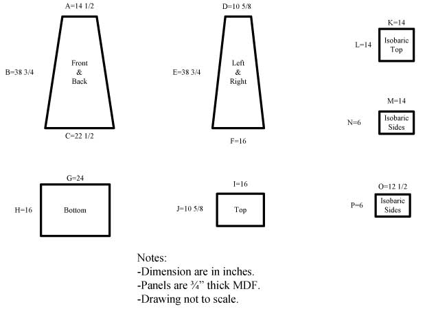
Tip: Refer to the Top and Bottom panels to see final box
dimensions.
1. Cut all panels to size. Mark each panel as noted in the cutout diagram
(Top, Bottom, etc). Note that because we are building a speaker with sloping
sides, not all of our cuts will be made with the saw blade set at 90
degrees. There is roughly a 5 degree angle at the top and bottom of each
panel to account for the slope of the box. Because of this angle, the Front,
Back, Left, and Right panels will have the shape of a rhombus if examined on
edge. For the Top and Bottom panel, this 5 degree angle is canted in toward
the center of the box – think severely squashed mini-pyramids. The interior
panels for the Isobaric Chamber can each be 90 degree cuts.
 Tip: There are a number of ways to make these cuts.
First you could use a table saw. This can be very accurate, but the largest
panels can be awkward to handle on the saw. What worked well for me was to
use a saw guide (available at many hardware stores) and a circular saw. The
guide can be clamped to the panel being cut to provide a straight edge to
guide the circular saw cut. Both methods use a 5 degree tilt in the saw
blade (from 90 degrees) to achieve the correct angle.
Tip: There are a number of ways to make these cuts.
First you could use a table saw. This can be very accurate, but the largest
panels can be awkward to handle on the saw. What worked well for me was to
use a saw guide (available at many hardware stores) and a circular saw. The
guide can be clamped to the panel being cut to provide a straight edge to
guide the circular saw cut. Both methods use a 5 degree tilt in the saw
blade (from 90 degrees) to achieve the correct angle.
Tip: Remember to account for the size of the saw blade when making the cuts
2. Find and mark the center lines (long and short
orientation of each, and therefore the exact center of each panel) of the
Right, Left, Top, and Isobaric Top panels.
3. Using the center line you just marked on the long
access, find and mark the 1/3 and 2/3 points along this centerline to divide
the panel in thirds.
 4. Mark each panel to indicate the intended
orientation of each panel. Mainly what will be the outside and inside of
each individual panel. This is important since the panels have a correct
orientation due to the angles required in the pyramid.
4. Mark each panel to indicate the intended
orientation of each panel. Mainly what will be the outside and inside of
each individual panel. This is important since the panels have a correct
orientation due to the angles required in the pyramid.
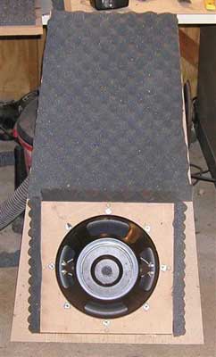
5. Cut the holes for the 12" drivers in the
Isobaric Top Panel and the Front panel. In the Isobaric Top, the center of
this hole is the 'x' you marked earlier in the center of the panel. The
center of the hole in the Front panel is somewhat flexible. I tried to go as
low as possible in the panel to maintain a low center of gravity (best to
keep this beast on its feet!) while allowing clearance for the Isobaric
Chamber. This turned out to be roughly 10" from the bottom or slightly under
the panel third marked above.
Tip: Verify the dimensions of the hole before making
any cuts. Use a tape measure or ideally the cutout template provided by
manufacturer.
Tip: To cut all these holes in the box, I used a Jasper circle jig and a
router. The circle jig is similar to the school compass (you know - you
always had to get one for school but rarely used it for anything but a paper
punch) that is designed to attach to the bottom plate of many routers to cut
nice clean holes. You could also get the holes made using a hole saw, jig
saw or something similar.
Tip: When using the Jasper circle jig, make sure that there is clearance
under the router bit or you could potentially put a nice smile in your work
bench – not that it EVER happened to me (I deny that I have photos)!
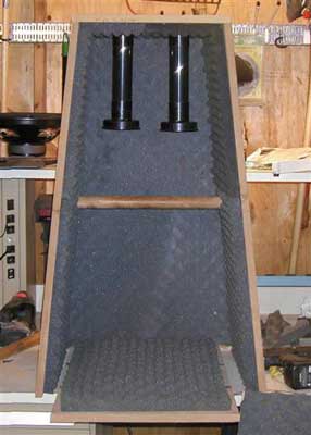
6. Cut the holes in the Top panel for the two 2"
ports. The centers of the cutouts for these ports are the Xs that were made
at the 1/3 and 2/3 points along the centerline of the Top panel.
7. Cut the 1" holes in the center of the Left and
Right panels marked out earlier for dowel cross bracing (these are holes through the panel).
Tip: Instead of a hole saw or circle jig, I used a 1-1/8" Irwin bit to make
the holes – the slight oversize helps account for the slope of the box -
just remember to use plenty of glue when assembling to seal things up.
Click Here to Go to Part IV.