|
||||||
|
The Mixer
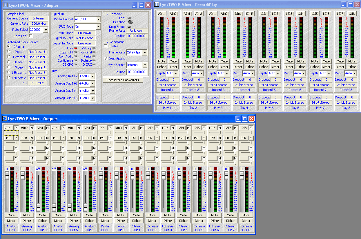
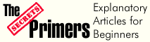
Click on the photo above to see a larger version. This mixer lets you configure the card for analog or digital input and output, monitor the signal level, and control the output of each channel. Window 1, called Adapter, is in the top left corner. Here, for example, you set the Sample Clock Source as Internal (clock derived from the on-board oscillator), Digital (clock signal coming from the Digital In connector), External (clock signal comes from Sync In connector), Video (NTSC or PAL from the Sync In connector - this would be used if you were synching the audio to a video signal), and other things. The Reference provides selection of the clock source reference type. The Digital In/Out Menu lets you select AES/EBU or S/P DIF, with SRC Mode On or Off. Analog Trim lets you set the Input and Output levels to either +4 dBu or -10 dBu. This gives you some flexibility in keeping input levels from clipping the preamplifier being driven by the Lynx card, and also keeps the sound card itself from being overdriven. The System Clock Rates window tells you which sampling frequency is in operation. Window 2, called Record/Play Inputs and Routing, is in the top right section (you can move the windows anywhere on the screen, the placement here is just for description purposes.) Here, you select and monitor the inputs being sent to each of the sound card's recording and playback busses. The Record Device Source Selection buttons (labeled AIn1 in the screen shot) control routing of an input source to a recording device. Each recording device can get its source from any one of 40 available inputs. To choose from this menu, you hold the mouse cursor over it, which causes a pop-up menu to appear. You can choose, for example, Analog In 1, Analog In 2, Digital In L, Digital In R, and others. Each input has a peak meter that goes up to 0 dB. You can mute any input/ You can add dither to any input (dither is controlled noise that actually benefits the sound). Dither can be added at 8 bit, 16 bit, 20 bit, or 24 bit depth. The Dropout indicator tells you if bits are being dropped. The third window, shown in the lower part of the figure, is the Output Section. It provides selection and level control of up to sixteen outputs. You can set any or all of the outputs to any particular channel. Looking at the example, you can see that I have set the first two channels to play Left and Right respectively, while subsequent channels are set to play from the left channel. What I do when performing bench tests on a multi-channel power amplifier is set all six to play from the left channel of a signal generator. That way, all channels of the power amplifier get the same signal. In this example, I set the output channels to play two independent signals, from the left and right outputs of the signal generator. For 5.1 digital surround sound, you would set the first column to play 1, the second to play 2, the third to play 3, and so on. The availability of numbered channels depends on the configuration of the sound card, and automatically appears for usage. In order to have 5.1 audio output, you need to configure your audio software which will decode the Dolby Digital or DTS if available, so that the output is sent to the LynxTWO, and of course, this all depends on what software audio player you have installed. You can mute each of these outputs as well as add dither.
|
||||||

Magazine Publishing Solutions by