| ||||||||||||||||||||||||||||||
|
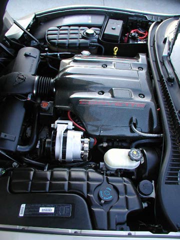
Introduction For our intro to car audio, we are now down to the actual install of the components we selected for our project car. The present article is is an overview of some of the install, and how it turned out. We will be doing a review on each component in depth in following articles. Power The first issue we had to address was the power needs. Just like at home, if the audio system doesn't have enough juice, the sound will suffer. The Corvette comes with a 110 amp alternator. With only 25% in reserve that left a little over 25 amps of current to work with for the audio system, and that is not enough for our install system. Although 110 amperes is plenty at home, remember, your wall AC is 110 volts. In a car, you only have 12 volts to start with. When you increase the voltage for the amplifier, you are still dealing with the basic 12 volts back at the battery, and this means a huge requirement for current. How to figure your power requirements: It's pretty simple. Add up the fuses on your amplifiers, then add up the fuses for the miscellaneous processors and changers. Here is our list:
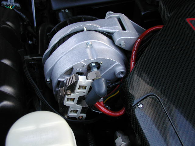
So as you can see, adding a possible 216 amp draw wasn't the best of ideas on the stock alternator. Since you usually will never see the maximum draw for a sustained period, it's safe to assume a 50% value for constant draw. On our system we assumed we will draw 108 amps under most usage. We then added this to our stock alternator and got a target of 218 amps. So off we went, and found a high output alternator (http://www.alternatorparts.com). The alternator featured an external heavy duty rectifier, and a 250 amp current rating. Perfect!
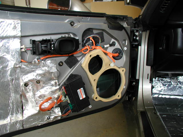
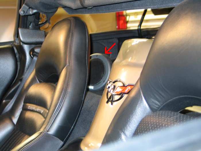
We installed the alternator and added a 4 gauge power wire to the existing factory wire. A 0 gauge ground wire was also added from the battery to the frame. In most cases, it's best to simply add to the existing factory power wires. Then we installed a spiral cell battery that had a high CCA (the CCA rating stands for the amperage that it can supply). Optima batteries are very well suited for the rigors of car audio. Phoenix Gold platinum stud caps were installed on the battery. Then we ran 0 gauge wire from the post caps to a Phoenix Gold 200 amp breaker. It's very common to see glass type or blade type fuses next to the battery for most installs. A breaker serves the same purpose, but allows you to purposely break the connection. This is handy when leaving the car at the mechanics, or when needing to adjust some part of the wiring. To top it off, a 1 farad capacitor was added to fortify the system. Often capacitors are viewed as an end all to poor system power performance. The truth is they offer nothing but to supply existing power a little faster. If you are missing that power due to a underrated alternator or battery, that big capacitor isn't going to help. Physical Layout Before we got to the trouble of measuring wire and screwing things in place, we laid it all out. This saves a lot of time. We wanted to install the equipment in a way that wouldn't interfere with the convertible top (no more than 4" high) and didn't take what precious trunk space we had. The obvious choice was to put the subwoofer in the back storage well and mount it flush. The amplifiers, power distribution, and processors, would all have to sit flush on the main deck. The capacitor, XM Radio, and six-disc changer would have to fit in the rear storage compartments. It was going to be a tight fit, but everything looked like it would go in . . . with a little work. The Main Speakers The factory speakers consisted of a large 7" inverted driver and 3" mid. The Dynaudio set didn't fit in the factory cutouts. We got to work making a template for the woofer and midrange. The problem was that they still wouldn't fit in the doors edge to edge. We thought up the idea of overlapping the mounting rings, and as a result, they fit with 1 mm to spare.
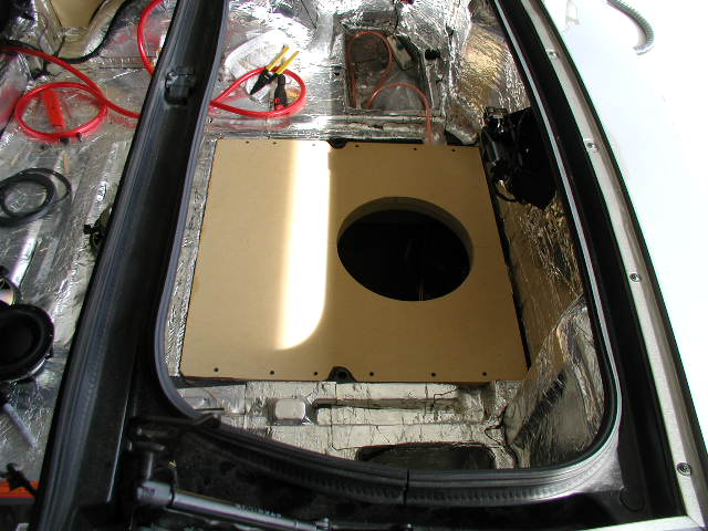
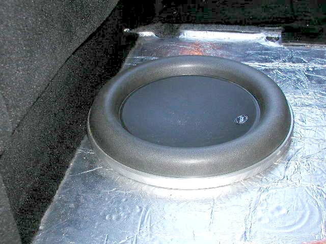
The Tweeters There simply wasn't room to mount the tweeters in the lower part of the door behind the grille. We also didn't want it that low, as it would negatively affect the sound stage. So we differed the placement to later. Now there was another problem. Where to mount the 3x5 crossovers? We used double sided foam tape, and cleaned the inside of the door with alcohol, then stuck them to the inside of the door away from the power window. Once in place there was no chance of moving them. The DynAudio 360 component set would be powered by the JL 300/2. The Subwoofer The JL 12W7 is not a small sub. It required some serious space, and in a Corvette, especially a convertible, that was a limited commodity. We looked at a few mounting options, and finally decided that we wanted to install it into the storage well. You might remember this from the article where we described damping. We cut a 1 inch thick piece of MDF to fit, and measured the resulting air space. Bingo . . . right on the money.
Some side supports and the top were glued into place with Liquid Nails, and completely sealed, also with Liquid Nails. After everything dried, I could lift the car 3 inches by the mounting plate. An additional 3/4 mount ring was added for some extra bite. I didn't want the 12W7 working its way out at 100 mph. A section of B-Quiet was then added across the entire work surface. There was no chance of an air leak. With just enough clearance to put the finish trim back on, it was a tight fit.
We ran some 10 gauge wire from the sub to the back deck. 1200 watts is a lot of power.
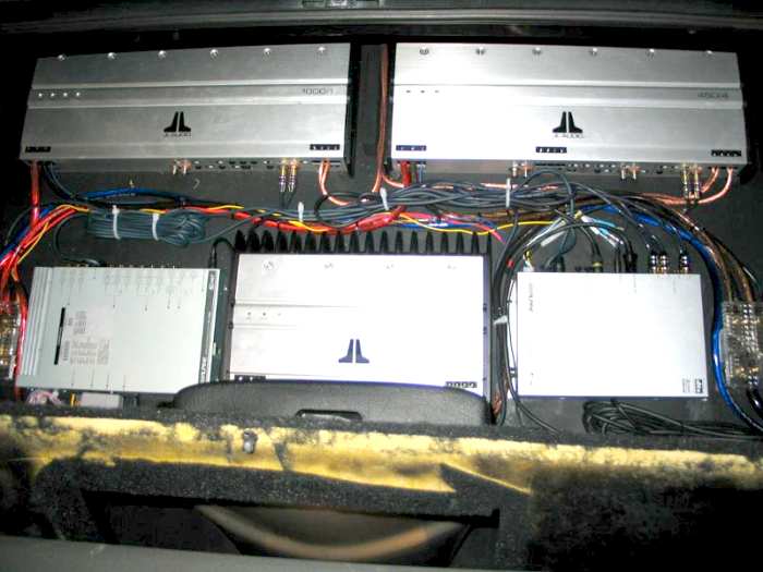
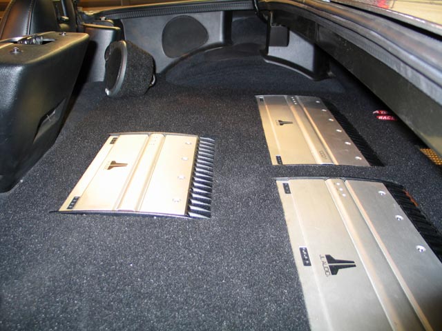
The Head Unit The main deck was a straight forward install. With a 1 DIN mount plate the unit slipped right into the factory 1.5 DIN location. The only cable needed was the Toslink and hideaway unit cable (HD). Those were run right down the middle of the car, away from the power cables. The D900 uses a DC-DC converter, a box that is about 3"x3". The power unit was hidden behind the ashtray. This unit provides a clean power source for the D900, so alternator whine is non existent. A 1/4 inch hardboard was cut to fit the rear floor. It was then glued in place. 1/2" strips were used to create the sides, and screwed into place. The equipment was then mounted to the hardboard. Power was run into the area, and the tangle of wires began. As you can see below, it was a VERY tight fit.
On the left is the hideaway unit portion of the Alpine IVA-D900. Lower center is the JL 300/2. Lower right is the PXA-H700. Upper Left is the JL 1000/1. Upper right is the JL 450/4. The power distribution blocks were located in the lower extremes. The Test Once everything was hooked up, we gave it a test drive. All the speakers worked, amps turned on, no fires. And . . . a very clean sound. Back to the garage we went to set the gains. Every amplifier is different. On the JLs we used a volt meter to confirm the maximum non clipping voltage specified in the installation guide. We used the gains to match this voltage to 90% of maximum volume on the head unit. We did this for each amplifier. After the gains were set, we proceeded to listen to our first CD. It was very promising . . . and very clean . . . BUT! We didn't have the surrounds in yet. Surround Sound Being the optimists that we are, we figured that since the factory locations were 5.25" and the Dynaudio's were 5.25" that there would be no issues mounting these speakers. Well, it turns out that the gas filler on the driver's side takes up some space behind the 5.25" surround. These speakers were so hefty, that they simply wouldn't fit depth wise. We considered making a custom panel, but such a cover panel was very complicated as it also covered the mechanisms for the convertible top.
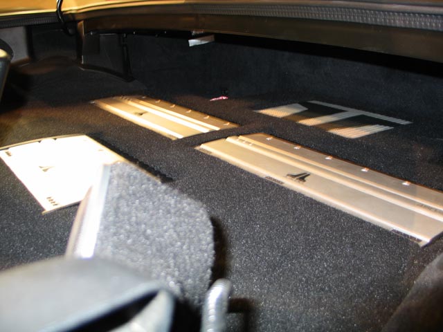
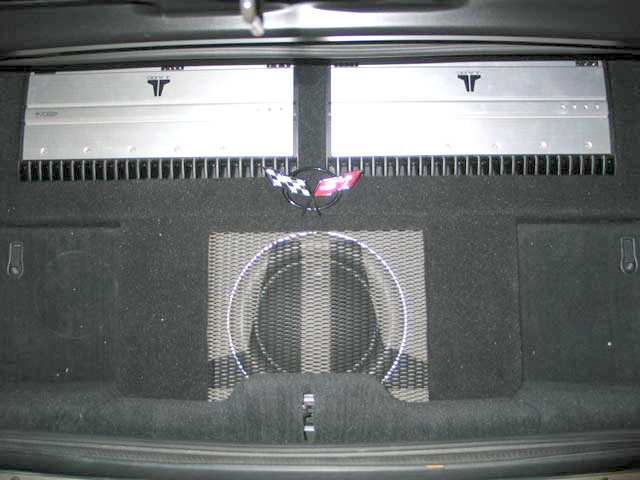
The next logical step was speaker pods. I had a local shop make some custom fiberglass speaker pods, and mounted them to the back deck. Much like how we position the rear fill in a home theater. I faced them to the center of the car to give the best imaging. The Finishing Touches As you probably know, the slowest part is putting everything back together. The carpet, padding, and plastic trim had to all be installed again. The seats, a few body panels, and the dash. A pattern of the amps was cut out of 1/4 hardboard and carpeted to match the interior. This piece was laid over the rear deck to cover the wiring and processors. Another trim panel was made for the subwoofer. The idea was that everything would be flushed into this false floor. The end result is very clean, and very attractive. Here are some pictures of the final install. Specifics of each component will be reviewed in the coming weeks. Thanks to all who helped with this project.
- Brian Weatherhead -
| ||||||||||||||||||||||||||||||


Magazine Publishing Solutions by