
|
|
|
Q I
(a reader) think there are a few errors in the article about negative
feedback on your Web page:
(1) It is not at all difficult to build an amplifier with zero
local or global feedback and retain adequate performance for audio.
For example, an amplifier I built (schematic at http://www.teleport.com/~lynno/IT-Triode-Amp.gif)
has a measured bandwidth of 17Hz to 63kHz at full power, and a
small signal bandwidth of 15Hz to 73kHz.
(2) Square waves are unaffected by reactive loads or power level, since there are no issues of phase margin stability to consider.
(3) Electrostatic shields on the power and input transformer remove RFI induction from power, input, and speaker cables, so there is no sync buzz with laserdisc, DVD, VHS, or cable-TV playback.
A (1) According to some engineers who have discussed the subject, the tetrode and pentode were developed specifically to avoid the inherent feedback of the triode tube so that they might control the feedback to fit whatever goals the design addressed. SET (Single-Ended Triode) amplifiers can be designed without feedback circuits, but that doesn't mean that they don't use feedback (the triode tube itself has feedback built-in).
(2) Square waves are simply sine waves with harmonics that continue to infinite bandwidth.
(3) RF interference with interconnects and speaker cable has nothing whatsoever to do with the power transformer unless it somehow affects the quality of the ground, in that the power transformer MAY put noise into the ground, and if it isn't of low enough impedance, may leak into the signal grounds, which theoretically are the same. Power transformers, like any transformers, are bandwidth limiting devices, and can filter out RF from the AC line, as does filter capacitance. Shielding the transformer may limit noise radiating from the transformer itself, but airborne RF is free to go at it regardless of shielding. It's up to the layout of the circuits, and the geometry/configuration of the cables to reject that RFI, or EMI for that matter.
![]()
Q (1) My Yamaha doesn't have bi-wiring capabilities, but I was just thinking about this for a Denon receiver with the Energy Take5 speaker setup, because the Denon's sub pre-outs are low-passed at 80 Hz. With the Take5's 90 Hz high-pass, it wouldn't matter what you set the sub's crossover to, because the 80 Hz low-pass in the Denon is not defeatable, so there would still be a small "hole" between 80 Hz and 90 Hz.
(2) On the news groups and other online forums, the Denon+Energy conundrum has been widely discussed. Lots of people were warning others, "don't buy a Denon receiver if you have Take5 speakers!" and vice-versa. I always thought this (bi-wiring idea) would be a workable solution, but I couldn't get anybody to confirm it.
(3) I'm wondering if you could explain something else to me. What exactly occurs to the signal, when you "cascade" low-pass filters? I've a BS in Mechanical Engineering, but I never learned much about crossovers and filters. I've heard that cascading low-pass filters (lpfs) causes only a phase shift (i.e., moves the -3 dB point), and I've also heard that cascading filters only causes a slope shift (i.e., -3 dB point stays put, while the slope increases from, say, 12 dB/octave to 24). Lastly, I've heard that both phenomena occur when cascading lpfs.
(4) The situations this usually comes up in, are with DPL and/or stereo receivers, since with DTS/DD, the crossover is matched in the decoder. However, say someone has satelite speakers and a DPL receiver with no "small/large" speaker settings. Assume also that the sub output has a non defeatable low-pass filter at 90 Hz, and the subwoofer itself has an adjustable filter from 60 -100 Hz. If their speakers drop off significantly (-3 dB) also around 90 Hz, then you would ideally want to set the sub crossover to 90 Hz also, for a "theoretically" flat response. However, with the sub output from the receiver being filtered, this changes things, because the sub will be "double filtered" or rather, the filters will be cascaded. What is actually happening to the signal here?
A (1) Maybe, maybe not. It depends on the slope, relative phase relationships (phase shift of the filter, the loudspeakers, and distance between the sub and sat), and specifically how low in amplitude they're at when they're at the crossover point of equal output, possibly at 85 Hz. If the output constructively interferes (in phase), and they meet 6 dB down at that point, you could very well get a flat response. I wouldn't buy a receiver, though, for bi-wiring capabilities. The dubious benefits of the method aside, you can bi-wire simply by running two separate cables from the same terminal. The only difference is that it splits outside of the chassis. For that matter, the only difference between bi-wiring and not is that it splits at the amplifier terminals instead of the loudspeaker terminals.
(2) Bi-wiring is somewhat controversial. I've yet to see a hint of solid technical evidence of any benefit. It does double the capacitance of a single-run, but does not affect the inductance in series with the drivers, nor lower the resistance between the drivers and the amps. Having two sets of terminals on the amp and the speaker does allow more contact area, though I don't think it's really a problem if you get a good connection to begin with. Still, it's nice to have all flavors to choose from. I have thought about ways that it could affect the speaker at the crossover region that the separate terminals are straddling, but I would't say that the effect I was pondering should be significant, and if that effect was of any benefit, it's only because the loudspeaker crossover wasn't designed very well. If the cables were of significant resistance, bi-wiring could theoretically cause a small peak in output in the crossover region where the impedance of the crossover/driver networks above and below were equal.
At the same time, doubling the capacitance that the cable contributes could elecit some audible artifacts from the amplifier which some interpret as a good thing, but I can't really claim to know exactly what people hear. The brain is a complex instrument. Lots of factors come into play. Some of them have to do with sound.
(3) It can do both. It simply adds more
poles to the filter. 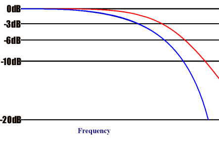 For instance,
in the diagram shown on the right, the red line depicts a low
pass filter, and if that filter were cascaded with an identical
filter, the output would look like the blue line.
For instance,
in the diagram shown on the right, the red line depicts a low
pass filter, and if that filter were cascaded with an identical
filter, the output would look like the blue line.
If you cascade filters with the same -3dB point, the -3dB point certainly will change, since the original point is now -6dB, and the -3dB point will have moved toward the pass side. The phase shift at that -3dB point will depend on the slope at the -3dB point. A fourth order (24dB/octave) Bessel filter, which rolls off gradually at the crossover point, will have less phase shift than a 4th order Butterworth filter, which approaches the final rolloff rate more quickly after the crossover point. Most audio filters greater than the first order variety are simply cascaded filters. The rest are DSP algorithms or transducers.
(4) You've got a filter whose slope is the
sum of the two filters. Setting the variable crossover just lets
you change the relative position of a couple, or a few of those
filtering stages. You can make the crossover lower than 90 Hz,
or you can make it 90 Hz and just change the shape of the rolloff.
Theoretically, you'd want to set the variable crossover substantially
above the 90 Hz point so that it doesn't make that -3dB point
-6dB, or -9dB, for that matter. On the other hand, if you have
a big full-range speaker, you would set the variable crossover
to fill in, and the 90 Hz filter would simply add a steeper limitation
on HF content that went to the subwoofer.
Q Your
review of the Yamaha DSP-A1 was quite informative and a deciding
factor in my purchasing the unit. However, in the review, it was
stated that the rear surround speakers volume could not be adjusted
individually. I have found a way to do so. The remote must be
set to parameter and the TEST button depressed so that the test
signals pan from speaker to speaker. Here, you can individually
adjust the L and R rear channels levels. This adjustment cannot
be done by using the LEVEL button for some strange reason.
A Thank
you very much for letting us know. The DSP-A1 is very popular,
and I think everyone who has one (including me) will appreciate
your discovery.
Q My
home theater is made up of very efficient Klipsch horns (104 dB/w/m
sensitivity) as the mains, Klipsch KV4 center (99 dB/w/m) and
almost equally sensitive surrounds. My roommate is moving out
and taking his Yamaha receiver. I plan on replacing it with an
amp-preamp combination. I like listening to movies at theater-like
levels. How powerful must my new amp be to blow me out of my chair?
I have been told that because of the high sensitivity of the speakers,
I would be able to save a lot of money on a less powerful amp
and spend a greater proportion of my budget on the preamp. My
question is, how low can I go?
A You
could drive such sensitive speakers with just about any receiver,
but because the quality of your speakers is very high, I would
suggest getting a good quality power amplifier to drive them,
regardless of the amount of watts the amplifier has. I recommend
getting a medium to high quality receiver that has a full set
of pre-outs, such as the Yamaha RX-V795 ($799) or the Yamaha RX-V2095
($1,599). Both of these products have plenty of power for the
Klipsch. You could also add a five-channel power amplifier, such
as the Carver AV-705 or the Adcom GFA-5500 and GFA-5503. Those
amplifiers would pretty much peel the wallpaper from your room
with sensitive speakers.
Q I
am a little confused about the 96kHz/24 bit DVD players out there.
Could you please clarify on this in relation to DD and DTS?
A Conventional
CDs have 44.1 kHz - 16 bit, two channel audio. DVDs can also have
this digital bitstream, but right now, they are being used to
carry DD and DTS, which are 5.1 channel audio at 48 kHz - 20 bit.
Two channel audio is also becoming available on DVD at 96 kHz
- 24 bit. The player decodes this latter format to two channel
analog before outputting it. At some point, I expect that we will
be able to get transports that output the 96/24 digital bitstream
for decoding with outboard DACs. 192 kHz (4 x 48) - 24 bit audio
is on the horizon, and it will also be a two channel audio format.
Both 96/24 and 192/24 will be on DVDs only, because they take
up too much space to be put onto conventional CDs that only hold
about 750 MB of data. CDs have room for DD and DTS, but only DTS
is being put on them at present. Burr-Brown has just announced
a 96/24 DAC chip that will also decode HDCD. Burr-Brown makes
some of the best DAC chips in the world, and they will be available
in products beginning in 1999, probably in high performance players
first.
Q If
I use two 200w/channel stereo amplifiers to bi-amp my speakers
(one amp for the left channel and one amp for the right channel),
how much power do I actually have per speaker? Is it 400 watts
or more? Or is it still 200w for the highs and 200w for the lows?
One of my friends says that their is a formula to calculate this
and that I effectively have more than 400w per speaker!!
A I
think you have bi-amping confused with bridging. With bi-amping,
you would still have a total of 400 watts per speaker (200 watts
for the tweeter and 200 watts for the woofer), assuming 200 watts
into an 8 Ohm load, and that you have 8 Ohm speakers, and lastly,
that you are using the crossovers in the speakers rather than
one between the preamplifier and the power amplifier. If using
a crossover between the preamp and power amp, you would get more
efficient use of the power amplifier, but it would basically be
the same amount of power.
Q When using the Video Essentials LD and the Delos Sound Spectacular test for speaker phase (and imaging), I have determined that my speakers were out of phase. However, I checked my terminals and black (-) was to black (-), and red (+) was to red (+). How then can my speakers be out of phase?
Usually, out of phase speakers means that the terminals got accidentally crossed during connection. This is not the case here as I have checked several times. Is there something I am missing? Yeah, it seems to fix the problem by reversing the ends on one of the speakers, but that means I have to connect the speaker-amp wiring wrong in order to get my system to play right. Wouldn't this mean the A1 is malfunctioning?
Since it takes such a long time to hook-up, I do not relish the thought of having to disconnect and send back (not to mention down time). Is there any other reason why this could be happening? This would be such an unusual defect for an amplifier. In fact, it would be the first time I have ever heard of such a thing.
P.S. Actually, the speakers seemed to not image nearly as well as when I had them connected to an older mid range Yamaha. Can an amplifier affect imaging? I thought this was a speaker characteristic. My speakers have not changed, nor has the furniture or placement.
If you can shed any light on this matter,
please explain. I am quite worried about the situation as I only
have fourteen days to return the unit.
A The
problem could be the result of several things. First, you should
test the speakers using a flashlight battery (1.5 volts). Remove
the speaker grille cloth, and connect the battery to the speaker
terminals by holding one wire against one end of the battery and
touching the other wire to the other end of the battery (use a
short piece of speaker cable, i.e., about 3 feet). You will see
the woofer move in one direction when connected. See if the woofer
on the other speaker moves in the same direction when using the
same polarity connection to the battery. If it does, then the
problem is in your electronics somewhere. If it does not, then
the speaker has been miswired. Next, make sure that the speaker
cables have not been terminated with the wrong color. Use a continuity
test by having one red speaker cable terminal connected to the
red speaker terminal, the red terminal on the other end of the
cable held against one end of the battery, and the other end of
the battery touched to the black speaker terminal. You should
see the cone move or at least hear a soft thump if there is continuity.
If there is not, then, one end of the speaker cable has been mislabeled.
Check both cables. Next, be sure to turn off any surround sound
modes or DSP modes when testing for speaker phase. On the Yamaha
this can be done by pushing the "Effect Off" button.
If it turns out that there is a polarity problem in the electronics,
it might be in any component, not just the receiver. That is something
which will have to be traced down by a repair shop. I think the
"imaging" differences you are experiencing are a result
of the more sophisticated DSP modes on the DSP-A1, plus the front
effects channels. The idea is that there are so many modes on
the DSP-A1, there is a high probability that you will find a few
that you like, and the rest can go unused. Try them all out, and
then, just stick with the ones you enjoy.
Q I
just purchased the new Toshiba 61" RPTV (with progressive
scan). I read that Toshiba has a new DVD player to be released
later this month (SD7108) that has a progressive scan output.
My question is, what would be the advantage of waiting for this
player vs. buying a quality player without this feature? P.S.
I bought the DSP-A1 per John's advice (over the *****) and am
beyond pleased with its performance.
A Progressive
scan will give you an image where the scan lines are much less
visible, because the entire frame (two fields) is shown all at
one time, with no interlacing. On conventional TVs, the image
is shown with alternating fields ("interlacing"), and
this emphasizes scan lines. Since you have the progressive scan
TV, I would definitely suggest getting a progressive scan output
DVD player to take advantage of that feature on the TV.