

Introduction to the HK 990 – A Truly Unique Stereo Component
The HK 990 is a truly unique stereo component. It is a dual domain device capable of accepting analog or digital inputs, converting domains as required, and sending the results to the speaker. A complex room-correction system
Specifications
- Design: Solid State Stereo Integrated Amplifier
- Power: 2 x 150 watts RMS into 8 ohms @ 20 Hz – 20 kHz, 2 x 300 Watts into 4 Ohms
- MFR: 10 Hz – 100 kHz
- THD: <0.07% at Full Output (8 Ohm Load)
- Analog Inputs: 7, Plus 1 Phono MC, 1 Phono MM, and 1 Balanced XLR
- Digital Inputs: 1 HRS-Link, 2 Optical Digital, 2 Coaxial Digital
- Analog Input Sensitivity/Impedance: 350mV/43k ohms for tuner/CD, 10mV/47k ohms for Phono-MM, 1mV/100k ohms for Phono-MC
- Digital Input Capability: All Standard Digital Formats
- Dimensions: 6.4″ H x 17.3″ W x 17.5″ D
- Weight: 43.2 Pounds
- MSRP: $2,599 USA
- Harman Kardon
- SECRETS Tags: Harman Kardon, HK 990
This review is independent of Tyler Stripko’s review published in June, 2011, where Tyler comments on a different sample. This review concentrates on measurements and internal design of the HK 990 and fits nicely together. Tyler covers the listening impressions.
Part II and Part III of the current review have also been published.
What Makes the HK 990 Unique?
When I am asked to select electronics for a new stereo system, I often surprise the questioner by recommending an AV receiver.
The overhead of an AVR for stereo can be costly: one is paying for stuff they are not using, including five power amplifiers, five DACs, and five digital volume controls. Obviously, cost savings are squeezed across the analog section to keep the price reasonable when seven, rather than two, channels of analog electronics reside in the box.
The video switching and up-sampling circuitry may represent half the price of an AVR, but have no utility for a stereo music system. Some functions of the DSP processing (e.g., Dolby and DTS
An ideal setup for the stereo enthusiast would have the AVR manufacturer jettison the superfluous stuff, upgrade the analog section, and alter the configuration of the front so setup adjustments can at the front panel, not on a TV screen. I have asked every manufacturer who sells AVRs and traditional analog stereo products when they will adhere to this roadmap; “never” is typically the answer on the belief sales volume will not justify the costs of re-engineering.
Harman Kardon must have had an epiphany for they are introducing the HK 990. The target market is high-end analog integrated amplifiers, not traditional stereo receivers; hence, the $2500 price tag. At that price, state-of-the-art analog and digital components are
The HK 990 shares the EzSet/EQ II digital room-correction system with the top-of-the-line $2500 AVR 7550HD as well as its bass management system for two subwoofers. Other current Harman Kardon AVRs use a simpler system.
The Analog Electronics
In the halcyon tube days of the 1950’s, Harman Kardon’s top of the line Citation products
The HK 990 amplifier is a direct descendent of the circuit topologies that Harman developed under Matti Otala. The exotic Otala design rules were intended to improve the sound quality of the unit. A search
Bob Cordell’s new text, Designing the Audio Power Amplifier, examines some of the issues that engineers face with Otala’s concepts. The Cordell text is a great read for those interested in the design of a modern amplifier with very different return-loop gain characteristics. The Cordell text requires some background in analog electronics. A book of similar spirit is Doug Self’s Audio Power Amplifier Design Handbook.
If you are attracted to the sound of an amplifier designed with Otala rules, then he may have been on to something. I will not opine, whether an Otala design is “closer to the truth” as Robert Lawrence Kuhn would put it for matters of cosmic significance.
I do not have access to
The only issue I identified on the analog side is a high 330pf capacitor at the input of the moving magnet
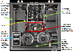
There is a red glow at the top of the HK 990. This is not due to the presence of vacuum tubes inside the unit. The glow is from the
Performance with High Resolution Files
High-resolution digital downloads are becoming more common, so any equipment you purchase going forward should have the capabilities to deal with them. From measurements provided by Harman it was clear that high resolution LPCMs streaming data from a file server made it from the SPDIF inputs to the DAC. This held true even if the room correction and bass management were active. If the high resolution files were recorded with wide bandwidth the Harman measurements show the HK 990 will pass spectral information to 45kHz.
The HK 990 lacks a USB port. Converters to SPDIF are relatively cheap for 96kHz sampling rates. 192kHz conversion is more problematic. The HK 990 does not support direct streaming of MP3, WAV, or FLAC. Almost no two channel DACs provide for this. The conversion must be done by the device storing the high resolution files. At some point, it is necessary to draw the line between the long-term standard like LPCM over SPDIF and what is constantly evolving and device specific (Apple Air Play). Replacing a $2600 unit every couple of years is not economical. Instead, use a lower cost unit to deal with all the permutations for file streaming and storage of today and next year.
Dual-Domain Tape Recorder Outputs and Tape Monitor Functionality

A dual-domain tape monitor should be a must-have for those seriously rooted in
More on the tape recorder interfaces will be found later in the review. One issue I do want to mention now is that mixing analog and digital connections may result in a recorder self loop and high-level oscillation that could damage your speakers. Properly connected this cannot occur.
Overview: A Three-Part Structure
My review has three segments. The first segment is the introduction that you just read, which highlights the special aspects of the HK 990, and this is a nice precursor to the rest of the segment, which examines the performance of the
Using block diagrams, the second segment considers the challenges of adding digital inputs and digital signal processing to a stereo integrated amplifier. This segment is a good read for those interested in the internal operation of an AVR at the block level. Since the HK is a stereo unit, the blocks are less complex. Once you have a handle of the operations at a block level, then the transition from two to seven, or even eleven, channels becomes more straightforward. The second segment also comments on the quality of the data converters in the HK 990 and additional performance data when the unit processes a high resolution file.
The last segment turns to the design and construction of the HK 990 at the circuit level. The analysis starts with the analog circuits in the direct mode, which is equivalent to an analog integrated amplifier. The designs of the power amp and
HK 990
The frequency of the correction in the HK 990 room-correction system can be limited to 1 kHz corrected. 1 kHz is slightly above the room-dominated region (500Hz). Full-band correction (to 20kHz) is also an option. The system not only makes the standard set of measurements at the listener’s
The near-field measurement is a unique feature of the HK 990. One assumes the room-correction system uses the near-field measurements as a guide for the EQ above 1 kHz. Above 1 kHz, a speaker’s near-field frequency response errors dominate over room related effects. Unfortunately, it is not as simple as making a direct near field measurement. The anechoic off-axis response of the speaker also affects what the listener hears. Harman may have guessed the end user has limited patience for making measurements at each speaker.
The HK 990 room-correction system supports two mono subwoofers with a separate room correction filter in each signal path. Harman Labs developed the multiple mono subwoofer technique to reduce
The four subwoofer technique also widens the room area where the response of the subwoofer is well controlled. A home theater with six to nine seats is the obvious application
The HK 990 cannot be connected to a computer to display pre- and post-corrected frequency response on a computer screen. This is a feature on some competitive systems. Disappointingly, a calibrated microphone is also not provided. By “calibrated,” I mean the microphone was placed in a test device with a reference microphone known to be flat. A file is created that represents the microphone error. The microphone is marked with a number that matches the file. When you set up a room EQ with a calibrated microphone, the first thing you do is enter the file into the processor, typically, a computer which interfaces with the electronics.
Anthem offers calibrated microphones starting with the entry level $1000 AVR.
HK 990 – Problems Identified in the Measurement of EzSet/EQ II
I made measurements of the HK 990’s operation over several months in two rooms. The rooms were equipped with two brands of full-range and two brands of satellite speakers. One subwoofer was deployed.
Three problems were identified with the HK 990 room-correction system:
(1) The level of boost below the port frequency of the speaker might exceed 15dB in the case of a subwoofer and 6dB in the case of full-range speakers. While the frequency response of the speaker appeared to be extended in acoustic response curves by this
The bass boost was evident under
(2) The subwoofer level, as calculated by the HK 990, was 6 – 8 dB low and required manual correction. Also, the crossover frequency selected by the unit was far too low. Manual settings appeared to be accurate with respect to the actual crossover frequency in my measurements.
(3) The EQ2 mode, appears from the measurements to allow a max EQ of approximately 2 kHz, does not work correctly. At the approximate 2 kHz transition point, the EQ does not return to 0dB insertion loss; instead, it holds at the transition point amplitude of the uncorrected response. This behavior raises or lowers the acoustic response above approximately 2 kHz and creates an unnatural result.
I examine how the HK 990 performs as it is shipped to the customer today. The developer of the EQ system in the HK 990 reviewed my measurements, and reported the problems found are real. On a hopeful note, the developer indicated the problems can be corrected with software. It is unclear if, or when a software update may be made available.
Best-Case Measurements for the HK 990
At the listening seat, I co-located my microphone with HK’s. I could make measurements to 20 Hz by setting the gate time
Normally, I would spatially average over nine points to reduce noise in the curves, but given the problems, I found myself making so many measurements with different speakers and rooms that there was no time to complete averages for each measurement. Without spatial averaging, the curves are too noisy to allow for 0.1 octave smoothing. As a workaround, I used a wide smoothing of one-third octave for the curves.
Figure 1 is a best-case result. The low-frequency room modes are well suppressed. Above 1.5 kHz the uncorrected curve and the corrected curve in the EQ2 mode match closely. The corrected curve was made with an Infinity Classia C336 speaker in the larger of the two rooms.

Figure 2 is the electrical correction of the HK 990 from the CD input (analog) to the
In Figure 2, I tried to normalize the scales of the acoustic measurements and the electrical correction curve measurements (Preamp out / CD in) to illustrate the one-to-one correspondence between the change in the acoustic response and the change in the electrical correction. Unfortunately, jamming two curves into one figure obscures the details. The electrical correction measurements alone are sized to take up the whole page in Figure 3. I show many electrical correction curves taken


HK 990 Performance with a Subwoofer
Figure 4 follows the same approach as Figure 2, but this time for a subwoofer. Black is EQ off and red is EQ on. The room modes of the post EQ subwoofer are well
This boost challenged the subwoofer. The frequency response of the subwoofer changed as the test level was increased. This indicates that a sliding EQ in the woofers overload prevention scheme was being activated

The electrical correction curve is illustrated in Figure 5. The subwoofer is also attenuated by 15

As this review was going to press (as we would say in the old days), I finally gained access to the designer of the EQ system. Our dialogue occurred several months after the measurements had been completed. The cause of the issue described above is a control mode found in the HK7550 video GUI that was not transferred to the HK 990. This is the subwoofer cone dimension mode, which runs from 8 to 15 inches. Subwoofer cone size is a proxy for the 6dB cutoff of the subwoofer.
I think many of you may have guessed what happened
I bring this up because someone is going to question my use of this subwoofer with a state-of-the-art integrated amp. My intent was to use two, thereby allowing me to determine how well the
Figure 6 shows the acoustic response of the subwoofer with the level selected by the HK 990 and the level of the satellite speaker selected by the HK 990 (top curve). The subwoofer is 7 dB
The setting of the internal crossover of the subwoofer can also create a level matching problem. Most systems like the internal crossover bypassed, but some prefer the filter to be set slightly higher than the desired crossover point. For these room EQs, the LPF of the subwoofer is cascaded with the LPF for the subwoofer in the DSP to save some DSP computations for the crossover which, in turn, can be used to correct other response errors in the subwoofer.
There is one other thing that can happen when the subwoofer crossover is bypassed: the SPL of the subwoofer is overestimated because the frequency range over which the uncorrected subwoofer is producing the test tone dwarfs the frequency range when the final LPF is incorporated. A good room correction system should compensate for this by filtering the subwoofers’ spectra before calculating the SPL.
Needless to say, I tried to get the HK 990 to work properly anticipating all these potential problems, but could not make an improvement. The fact the subwoofer was set to the 15inch mode may have caused an internal SPL estimation error. The engineers at Harman could not confirm this idea, but given the 30dB correction range was introduced with the 15 inch subwoofer setting, such a problem would not be outside the realm of possibility. A revised HK 990 with a 10 inch setting should not show this problem. If it is a real problem, Harman is aware of it now and will put it on the punch list of corrections to be implemented if the software is updated.

Deep Dive to Examine the EQ 2 Setting
Figures 7 – 19 explore the problem with the EQ 2 setting. I am going to spend some time with this issue even though Harman says they can correct it with the software fix because I have seen it in
Figure 7 is set up like Figure 2. Again, the Infinity C336 is used, but in a different position. Now the EQ 2 curve (red) does not match the uncorrected curve (black) above 2 kHz. Instead, the entire curve shifts down 2 dB. Looking at the electrical correction curve makes it clear why this happened: the red curve of the electrical correction plot has not returned to the black curve (0 dB insertion), but stays 2 dB down.

Figure 8 shows the electrical correction curve

Figure 9 refers to a competitive high-quality speaker, which I call P. I am not identifying it because the single shoot measurement at one-third octave smoothing belies the speaker’s true performance. It is in position 3 in the larger test room. Now the red curve in the acoustic measurement (EQ2) above 2 kHz is above the black curve by about 1 dB. The speaker brightens with this offset above 2 kHz and is clearly less flat with EQ applied. Again, the electrical correction curve shows the problem: above 2 kHz it is 1 dB above the 0 dB insertion curve (black).

Figure 10 illustrates the electrical correction curve

Figure 8 had signal attenuation above 2 kHz, but
Figures 11 – 15 reveal why the EQ2 curve above about 2 kHz (

In Figure 12, note the electrical correction

Figure 13 highlights a 1.5 dB shift above unity gain. The level of the correction curve is matched at 1.2 kHz. The respective lifts of Figures 12 and 13 brighten the speaker.

Figures 14 and 15 are electrical correction curves where the correction curve is below unity gain at 2 kHz. The EQ2 curve above 2 kHz now shows a loss of about 3 dB for both cases. The cut in gain in Figures 12 and 13 dulls the speaker.


Understanding the Problem with EQ2: An Alternate Perspective
The Anthem ARC room EQ (Figure 16; a full set of measurements will be presented

Figure 17 illustrates the response of the HK 990 to this condition if its maximum correction frequency were 700 Hz. The HK 990 would brighten the speaker’s sound by setting the level at the peak, which is about 2.5 dB.

With the same speaker and the maximum frequency of the Anthem ARC at 1.5 kHz, there is a dip (Figure 18). The Anthem ARC gravitates to the dip (red on top of green), signaling a shift of electrical correction curve to unity gain above 1.5 kHz.

Figure 19 shows what the HK 990 would do. The curve above 1.5 kHz matches the level of the dip and the electrical correction curve is 1.5dB down above 1.5 kHz.

The EQ 3 Setting: A Detailed Interpretation
Looking at the curves in Figure 10 – 15, it can be seen EQ3 (blue curves in the measurements) is reducing the top-end of the speaker, above 1 – 3 kHz depending on the speaker and room placement. The setup for figure 12 is the exception. EQ3 made the speaker sound different than its intrinsic voicing It is a matter of preference whether EQ3 is an improvement over no correction.
Since EQ3 appeared to be working properly for full range speakers from the data above I committed

Figure 21 below is the pre- and post-equalized response

The
Harman engineers were not able to address whether EQ3 was performing properly. The step starting at 500Hz suggests a problem matching the near-field correction curve to correct variations in the speaker’s response to the part of the curve corrected for errors due to the room. They also could not confirm if the downward slope above 1kHz is the desired result.
There is a lift above 8kHz at the post correction response. I expect, but cannot confirm, if this is the result of the microphone’s top end response dropping. The system cannot tell a drop in level at the microphone from one occurring from the speaker. Accordingly, the software infers the speaker needs some lift in the high end. I have seen this problem in other room EQs with
I am not overly concerned about the EQ3 issues. EQ3 is designed to correct a poor response curve (rough or significant octave-to-octave variation) of the speaker and it is unlikely someone would spend $2600 on the HK 990 and match it to bad speakers. Not all speakers that
Subjectively (and this is my sole subjective observation), the correction below 400Hz before the bass push is similar to my preferred EQ systems. The push in the bass was not as artificial sounding as I have heard with AVRs whose EQ systems also attempt to flatten the frequency response below the port frequency. The AVRs’ amplifiers did not have the current sourcing ability of the HK 990. The parallel configuration of the Infinity C336’s three woofers makes it difficult to drive when the gain is up 6dB. To confirm this observation, the distortion of the speaker in the area that the room EQ has pushed the bass must be measured. In my lab, these measurements are not feasible owing to my combined problem of high ambient room noise at low frequencies and close-in neighbors with little tolerance for 35Hz test tones. In any case, the C336 speaker sounded better with amplification when used with the Anthem ARC room EQ that prevents bass-push. Since the Anthem ARC is PC-based, post-corrected bass response can be panel
The EQ off is not normalized to EQ3 as can
I will leave it to Tyler to tell you if this target curve
Conclusions About HK 990 Room EQ
With the addition of digital room-correction, the HK 990 travels into unique space for a stereo integrated amplifier. As a dual-domain device, its internal electronics are conversant with analog or digital inputs, including high resolution files. Recording from digital and analog sources is simplified. In addition, the HK 990 has no mechanical controls for improved reliability, improved gain tracking, and increased stereo separation. Unfortunately, the room EQ does not function properly in many operating modes. We can hope Harman patches the code. The engineers at Harman clearly understand what needs to be changed. It remains hazy whether these changes, if made available, will be available to products already sold, available only with a change at a service department, or something that can be done in the home. The timeline for these fixes also remains an open issue.
In Part II of the series, I examine dual-domain signal flow of the HK 990
FEATURED COMMENTS
Written by Donnie
I’d like to see interior pics
Seems like a great piece from a company with the potential to make great gear.
____________________________________________________________________________________________
Re.
Written by David Rich
Donnie,
Tyler Stripko published pricing, specifications, setup, use, and listening impressions in June. Refer to the link at the beginning of this review. I have two upcoming parts to be posted October 27 and November 3. The next part begins with an interior picture and examines the unit’s configuration at the block diagram level. More details about the contents of my review are at the bottom of page 3.
____________________________________________________________________________________________
Thank you
Written
I am absolutely astounded! A technical review that offers insight into the deficiencies of a product?
Simply outstanding! I haven’t read a review this good in years. This is why I visit this website every month or so, in hopes of finding the rare article that contains actual substance.
Thank you, thank you, thank you!
-
?
CLICK TO VIEW MORE COMMENTS
2-channel receiver with room EQ, almost complete…
Written by Maarten, October 24, 2011I also use a multi-channel receiver in a stereo setup. My Audessey takes care of speaker EQ, including the subwoofer and crossover
A stereo component with room EQ is great. What I am
missing however , are HDMI inputs that accept DSD streams and the latest high def surround formats. I hope more companies will make stereo receivers with room EQ. Good informative review by the way! I look forward to the sequels.____________________________________________________________________________________________
Re. Thank you
Written by David Rich, October 25, 2011Vinh
Your words are much too kind. My acoustic measurement tool (AcoustiSoft RplusD) is a primary reason I can detect problems and clearly illustrate the issues to the reader. The versatility of the low cost AcoustiSoft RplusD, written by Doug Plumb, is exemplified in the review.
Please do not stay away for a month. There is a wealth of a material on the site similar to this review. The Secrets Blu-ray Player HDMI Benchmark series is a good example. Part 2 of this review is scheduled to appear on Thursday.
____________________________________________________________________________________________
Software Update
Written by Manendra, November 25, 2011Dr. Rich,
It has been over a month since your review. Has there been any news from Harman engineers regarding an updated software to correct the issues you have identified in your review?
____________________________________________________________________________________________
Software Update
Written by David Rich, November 30, 2011We are in contact with HK on a regular basis and will update our readers when new information becomes available
____________________________________________________________________________________________
ARC Review
Written by Johkan, April 23, 2012Dr. Rich,
You referred to Anthem’s Room Correction in your HK review and I was wondering if a review of that system was in the works
John
____________________________________________________________________________________________
ARC Review
Written by David Rich, April 24, 2012Yes, a review is in preparation for the ARC system and the NHT subwoofer. The Anthem ARC is one of the room-correction systems that
requires a PC. PC control which was highlighted in the SECRETS Best of 2011 Awards for Technologies on the Rise:www.hometheaterhifi.com/best-of-awards/1450-secrets-best-of-2011-awards.html?start=3
ARC also won the Best Advanced Room Correction Firmware Award for 2011.
Optimal correction to match a subwoofer’s performance is one of the PC-control options in the ARC firmware. ARC proved readily compatible with the NHT subwoofer.
David Rich
____________________________________________________________________________________________
15″ subwoofers, only?
Written by JohnyBGood, May 13, 2012I just ordered this unit. I forget if I read it here, or elsewhere, but w/ 2 subwoofers connected the room correction EQ of the HK 990 uses more than one listening location for
mic placement, thereby providing greater flexibility. Does that mean I have to buy 2 15″ subwoofers to take advantage of this, since the HK 990 assumes I’ll be using 15″ subs? Or do I buy 2 subwoofers that go as low as 15″ subwoofers (if so, what range am I looking for?)? Obviously I’m a bit confused. Thanks.____________________________________________________________________________________________
…
Written by David Rich, May 17, 2012When multiple mono subwoofers (all connected to the single subwoofer output port of a system with standard bass management) are optimally placed in a room, it is possible to minimize
variations of the frequency response from seat to seat:www.harman.com/EN-US/OurCompany/Technologyleadership/Documents/White Papers/multsubs.pdf
The HK 990 has a separate output for each mono subwoofer. With added signal processing, this permits greater freedom in placing the subwoofers, while retaining near-optimal performance.
I used a 10 inch subwoofer when testing the HK 990. As outlined above, the unit did not work correctly for a woofer of this size, and I did not proceed to test the compatibility of the unit with two subwoofers.
The test results suggest a subwoofer with bass extension to 20Hz should not exhibit these problems, but I did not verify this. In the two subwoofer
mode of operation I cannot comment on the relative performance with different models of subwoofers that offer the 20Hz extension compared withmatched subwoofers.The HK 990 requires three placements for the microphone with two subwoofers; with one or none, the microphone has a single placement.
When opting for an expensive second subwoofer, consider purchasing an acoustic measurement system to see the frequency response at the listening seats and to ensure the subwoofers are placed so the system is
minimizing variation of the frequency response from seat to seat. You will also be able to see if changing the subwoofer placements improves,degrades or has no effect on the result.The measurement system will also validate the crossover point, phase and amplitude of the subwoofers (figure 6 in this review). For the measurements to be accurate you must use spatial averaging of multiple microphone positions around each listener’s seat (figures 20 and 21 in this review). The AcoustiSoft RplusD system used in this review has these capabilities.
David Rich